14 field servicing – Cloud Electronics CX-A6 User Manual
Page 9
CX-A6 I
NSTALLATION AND OPERATION MANUAL
8
15-01-09 V9
9. Align the two holes in the module over the top of the two spacers.
10. Secure the module with the two M3x6 screws (removed earlier).
11. When installing a Bose
equalisation module to a stereo EQ adapter, remove the
adapter jumper link for the channel to be equalised and fit the Bose® EQ module to the
appropriate connector
12. When installing a Bose
equalisation module, configure the relevant 65Hz filter to ‘IN’
and connect a CXL-100T 100V line transformer (see section 6)
13. Fit the top panel.
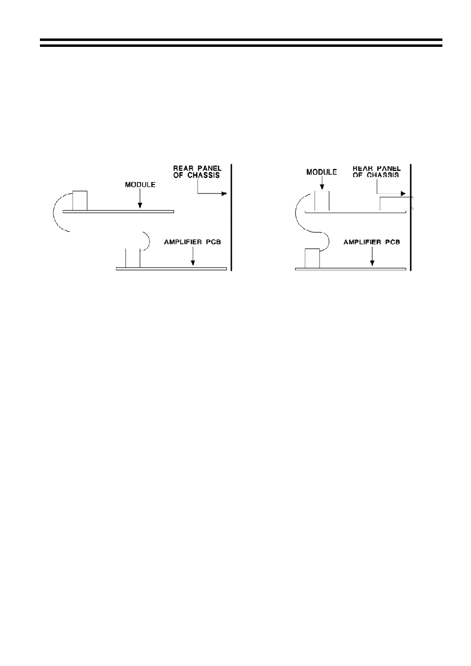
Bose
Equalisation Module Orientation (Side View) VCA Module Orientation (Side View)
14
Field Servicing
The CX-A6 is ruggedly built and uses proven reliable circuitry. It requires no more than
the occasional removal of any dust that may have built up inside the unit as a result of the
forced cooling. In the unlikely event of failure, the power amplifier module (2 channels)
can be replaced without special tools and is available as a tested replacement complete
with heat sink. Proceed as follows to replace the power module:
Disconnect all the leads and connectors from the rear of the unit.
Ensure that the mains supply lead has been disconnected.
Remove the CX-A6 from the equipment rack.
Remove the top panel.
The power amplifier modules are arranged as three dual channel units.
Locate the faulty unit and remove both the 7 way power cable & the 10 way ribbon
connector.
Remove the four fixing screws from the bottom of the unit to release the module.
Now fit the replacement unit by proceeding in reverse order.
No setting up is required and the unit should operate normally.