8bridged mode operation, 9status indicators – Cloud Electronics CX-A6 User Manual
Page 6
CX-A6 I
NSTALLATION AND OPERATION MANUAL
5
15-01-09 V9
7
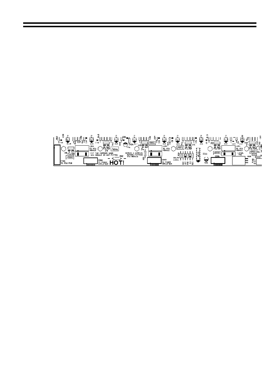
Configuring the CX-A6 for 100V-line Operation
When a CXL-100 is connected to a channel of the CX-A6, that channel must have its
65Hz high-pass filter operational. Without this filter operational, the presence of high
input levels at frequencies below 50Hz may result in transformer saturation causing the
amplifiers VI limiter to operate. The filter can be switched on by moving the relevant
jumper to the ‘IN’ position.
Jumpers J1-6 are associated with the channels of the CX-A6 as follows:
J1 = Zone 1
J2 = Zone 2
J3 = Zone 3
J4 = Zone 4
J5 = Zone 5
J6 = Zone 6
Diagram to Show Location of J1-6 on the CX-A6 PCB
8
Bridged Mode Operation
The unit can operate in Bridged Mode using any two channels. The inputs must be wired
together by linking the input signal at the XLR connectors of the two relevant channels,
wiring the "second" input out of phase (i.e. pin 1 ground, pin 3 in-phase, pin 2 reverse
phase). The input level controls of the two channels should both to be set to the fully
clockwise position.
The output load should then be connected between the terminals marked “CHx” (where
“x” represents the channel number) of the output connectors of the relevant channels.
There is no connection to the terminals marked “0V” of the relevant channels.
You must ensure that the positive wire is connected to the terminal marked “CHx” of the
“first” channel used. The negative wire is connected to the terminal marked “CHx” of the
“second” channel used, i.e. the channel with its input connected out of phase.
Thus for example it is possible to configure four of the available channels as two bridged
outputs allowing a stereo input to be delivered to two 240 watt 8 ohm outputs.
9
Status Indicators
The front panel of the CX-A6 has an array of LED’s that indicate the status of all six
channels. The lower green LED illuminates when a signal exceeding 500mW is detected,
the yellow 'peak' LED will illuminate when the amplifier output is close to clipping and the
top red LED indicates that the protection relay has disconnected the load. Please note
that it is normal for all six red LED's to illuminate for approximately five seconds when the
unit is switched on, indicating operation of the switch-on delay circuitry. The lower green
LED indicates that the power is switched on.