Rear panel description – Cloud Electronics 36-50 User Manual
Page 11
36-50 Installation and User Guide V1.0
11
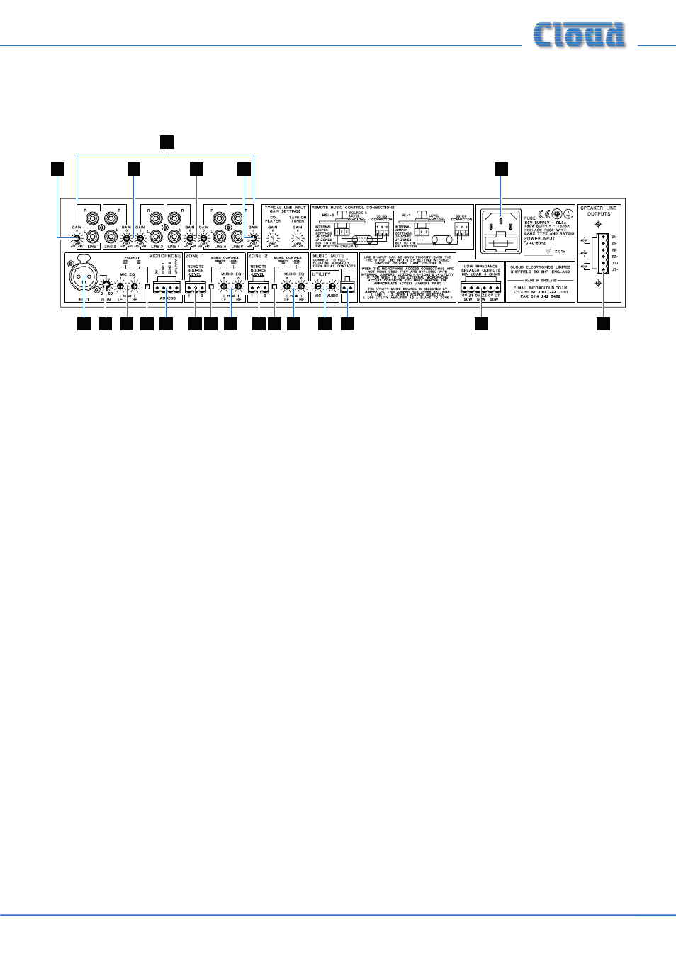
Rear panel description
2
2
2
2
15
1
3
4
5
6
8
10 11
11
10
8
9
12
14
13
7
1.
LINE 1 to LINE 6 – 6 pairs of RCA (phono) sockets for connection of music sources. Inputs are stereo, summed internally
to mono. See page 12.
2.
GAIN – preset trim control for each line input, providing ±10 dB of gain adjustment for input level matching. See page 16.
3.
MICROPHONE INPUT – balanced microphone input on 3-pin female XLR connector. See page 13.
4.
GAIN – preset mic gain control, gain range 10 to 60 dB. See page 16.
5.
MIC EQ – HF & LF preset EQ controls. See page 17.
6.
ACCESS – 4-pin 5 mm-pitch screw-terminal connector for per-zone paging access by contact closure. See page 13.
7.
PRIORITY – activates Automatic Voice Over (AVO) mode, giving immediate priority to announcements made via the mic
input. See page 18.
8.
MUSIC EQ – HF & LF EQ adjustment for each zone output. See page 17.
9.
UTILITY MIC & MUSIC – two pre-set controls, adjusting the level of the microphone input and chosen music source
respectively at the Utility Output. See page 17.
10.
REMOTE SOURCE + LEVEL – 3-pin 5 mm-pitch screw terminal connector for each primary zone, for connection of
RL-1/RSL-6 remote control plates. See page 14.
11.
MUSIC CONTROL SWITCHES – determine whether front panel music source and level controls will remain active
when remote control plates are connected (per-zone). See page 14.
12.
LOW IMPEDANCE SPEAKER OUTPUTS – outputs for each of the three zones (two primary plus Utility output) on
3-pin 3.5 mm-pitch screw-terminal connector. See page 15
13.
SPEAKER LINE OUTPUTS – location of output terminals for 70 V/100 V-line operation when CXL-3120 transformer
module is fitted internally (either on Model 36-50T, or as retrofitted option). See page 15.
14.
MUSIC MUTE – 2-pin 5 mm-pitch screw terminal connector for connection of external emergency muting relay (e.g. fire
control panel). See page 15.
15.
Mains – fused IEC receptacle for AC mains (includes storage for spare fuse). See page 12.