Ò³ãæ 7, Unit parts identification – Campomatic Window AC User Manual
Page 7
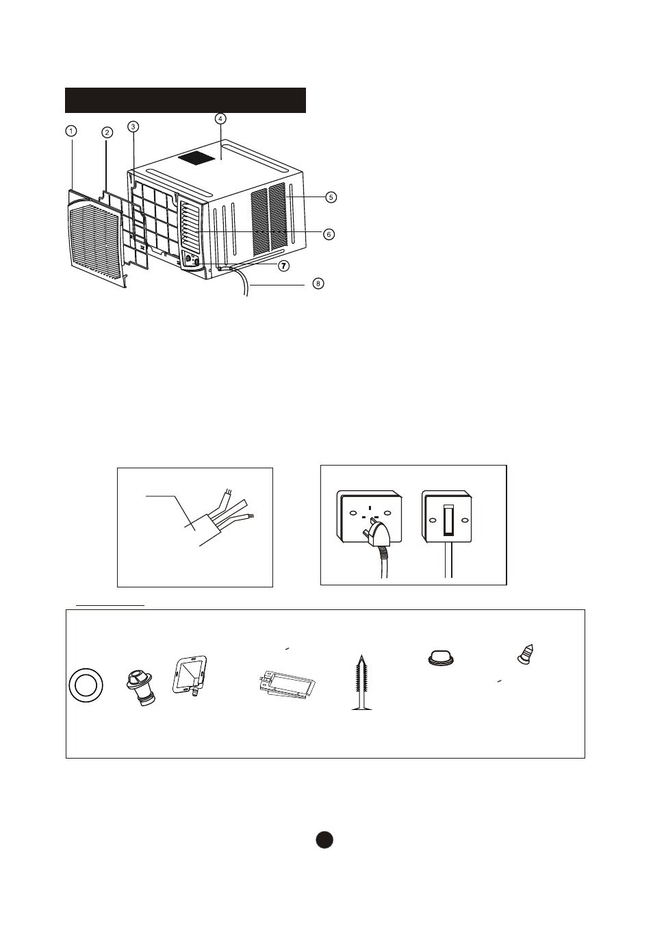
1. Front panel
2. Air filter
3. Frame
4. Cabinet
5. Air inlet grille (outdoor side)
6. Air outlet grille
7. Operation knob
8. Power supply cord
UNIT PARTS IDENTIFICATION
1. Power cord conductors are distinguished according to color as follows (see Fig.1)
2. For your safety and protection, this unit is earthed through the power cord (see Fig.2)
Please contact the manufacturer or its service agent or a similar qualified person if
you want to replace it.
3. Be sure that the unit being correctly grounded. The wall outlet (Air-break switch)should be
provided with reliable earth wire.
4. The unit should be provided with an individual circuit and the circuit breaker/fuse
rating should be the same as that of the power cord and wall outlet.
POWER
CORD
A
E
N
E-Earth wire, yellow/green
N-Neutral wire, blue
A-Active wire, brown
Fig.1
Fig. 2
Wall outlet
Air-break switch
Accessories
Seal
(Used on
drain joint)
1
1
Screw
2 (For >18000But/h models only:
Used to fasten the front panel)
2 or 4 (For cooling & heating
models only: Used to install the
drain tray)
Drain Joint
1 pec
Drain Tray
(Cooling & Heating
models: >16000Btu/h)
1pec
Drain Tray
(Cooling & Heating
models: <16000But/h)
Rubber Plug
NOTE:All the illustrations in the manual are for explanation purpose only.Your air conditionar
may be slightly different.The actual shape shall prevail.
1or 2
(depend on type you purchased)
or
8
Wooden screw
(optional)
4
4