Burst Electronics F2B User Manual
Page 4
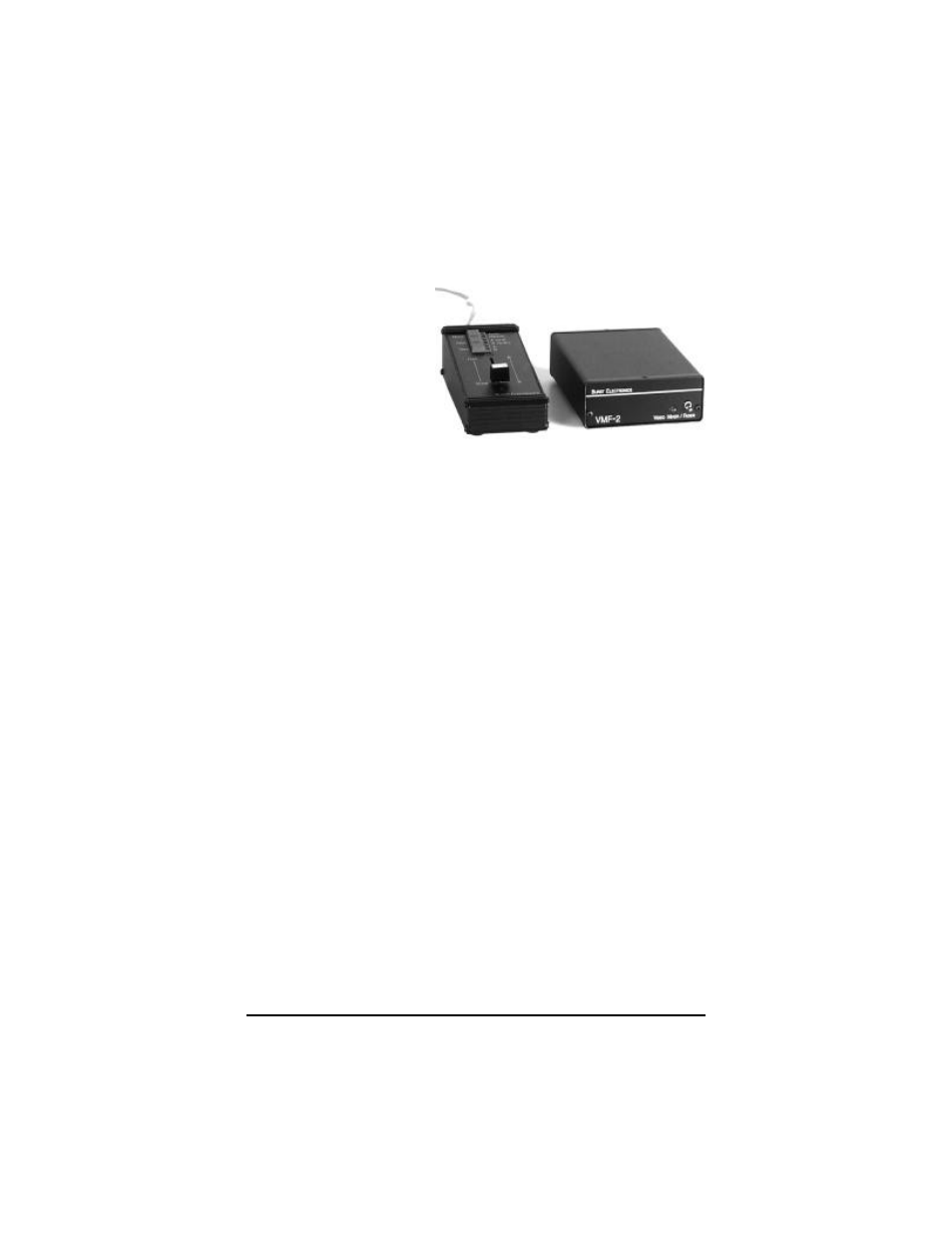
Model VMF-2 Mixer/Fader
The VMF-2 Video Mixer/Fader will accept two
synchronous
(genlocked) inputs
and smoothly fade
between them.
Another feature is
the ability of the
VMF-2 to fade the
“A” channel to
Black. These
actions are controlled by the fader bar.
Connections
Interconnect the VMF-2 Head End unit with the
Remote Control Unit (RCU) using the RJ11 cable
attached to the RCU. Burst Electronics supplies a
3’ (1 meter) cable. This cable may be lengthened to
a maximum of 25’ (8 meters).
Connect the two video sources to the two inputs, A
& B. The sources must be synchronous (genlocked)
for a smooth transition from A to B. The output is fed
to a monitor, VTR, etc. If the application is for
Channel A Fade to Black only, then no B input is
required.
There are internal 75 Ohm terminations for each
input channel. If you want the input unterminated
(HiZ), first remove the two screws holding the front
panel on the Head End unit. Remove the front panel
and slide the top cover forward about two inches.
Remove the jumper from the appropriate input
(labeled W2 for channel “A”, W1 for channel “B”).
Replace the top cover and front panel.
Video Mixers & Faders
2