Con-o operating instructions cont’d, Wiring diagram / bug-5100-f dc iii drive unit – BUG-O Systems CON-O User Manual
Page 7
7
TORCH
The
Torchholder (V) will accept any standard American machine torch
[barrel diameter 1-3/8" (35 mm) with 1/4" (6 mm) square 32-pitchrack]. The
32-pitch pinion is standard. The
Twin Hose Assembly (BB) connects the
torch to the
Quick Acting Manifold Assembly (AA). The supply hoses are
to be connected to the open side of the
Quick Acting Manifold Assembly.
Proper torch operation is essential to quality cuts. We suggest that you follow
the torch manufacturer’s instructions carefully, being sure to use a clean tip
of the proper size.
To reach maximum cutting diameter capacity with the
CON-O machine, you
can use an adjustable tip attachment which maintains the centerline of the
offset tip in line with the torch body or you can use a bent or angled torch tip.
The contouring capacity with this machine system, is limited to two-thirds of
the diameter of the cylinder in which the cut is made; i.e. and 8" (200 mm)
hole maximum in a 12" (300 mm) cylinder.
POWER SUPPLY
The DC III drive operates on 120 volt, [42 VAC], [240 VAC], 50/60 Hz. The
Circuit Breaker (DD) protects the unit against overload or electrical faults.
CAUTION: IF THE CIRCUIT BREAKER OPENS, FIND AND CORRECT THE
CAUSE OF FAILURE BEFORE RESETTING.
DC DRIVE UNITS - SPEEDS
The standard speed for the DC drive is the speed at the pitch circle of the
Ring Gear (K), which is 18" (460 mm); 27" (685 mm) and 36" (915 mm)
respectively for the
CON 3, 4 and 5. The speed at the cutting circle is directly
proportional to the diameter of the cut at given speed setting.
EXAMPLE: On a CON-3303, the pitch circle is 18" (460 mm). To find the
speed range at *” (200 mm), use the following ratio: [Speed range at 18" pitch
circle is 2-50 ipm (50-1270 mm/min)].
CON-O OPERATING INSTRUCTIONS CONT’D.
IPM
Minimum: 8 = 18;
18 x = 16;
x = 0.88 ipm
Maximum: 8 = 18;
18 x = 400;
x = 22 ipm
Minimum: 200 = 460; 460 x = 10,000;
x = 22 mm/min
Maximum: 200 = 460; 460 x = 254,000; x = 552 mm/min
x
2
x
50
x
50
x
MM/MIN
14
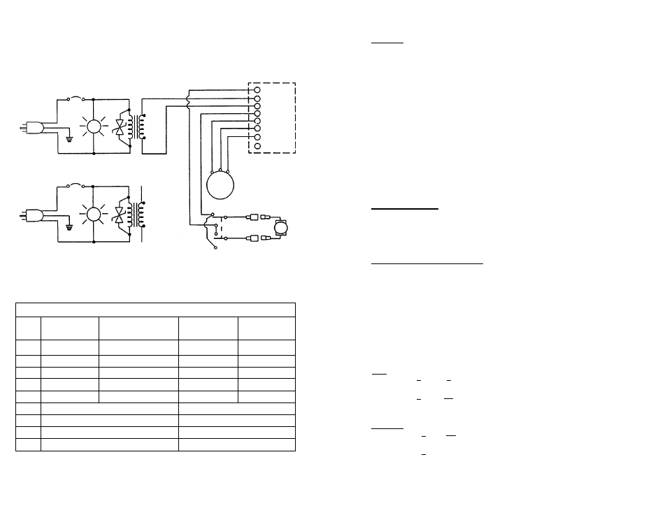
WIRING DIAGRAM / BUG-5100-F
DC III DRIVE UNIT
BUG-5100-F
120 VAC
BUG-5100-F
42 VAC
ELECTRICAL COMPONENT CHART
ITEM DESCRIPTION BUG-5100-F
BUG-5102-F
BUG-5104-F
120 VAC
240 VAC
42 VAC
A
Power Cord
BUG-9445
GOF-3115
BUG-9442
CB Circuit Breaker CIR-5247 (.7A)
BUG-2952 (.5A) BUG-2933 (2A)
D
Pilot Light
BUG-1415/BUG-1415-A BUG-1428
BUG-1427
V
Volt Trap
BUG-1393
BUG-1563
BUG-1393
T
Transformer
BUG-9675
GOF-3112
BUG-1468
M
Gear Motor
BUG-1550 (150:1)
F
Precision Speed Control
BUG-1725
S
Toggle Switch
BUG-2255
P
Potentiometer Control
BUG-9686
PART NUMBER
BUG-5102-F
240 VAC
A
D
A
D
V
M
P
8
7
6
5
4
3
2
1
CB
BLK
GRN
WHT
V
CB
BLK
WHT
GRN
WHT
BLK
T
TAN
TAN
RED
DK. BLU
DK. BLU
YEL
WH/BLU
F
S
PK
GY
RED
BLK