Operating instructions – BUG-O Systems BUG-9870 User Manual
Page 7
7
OPERATING INSTRUCTIONS
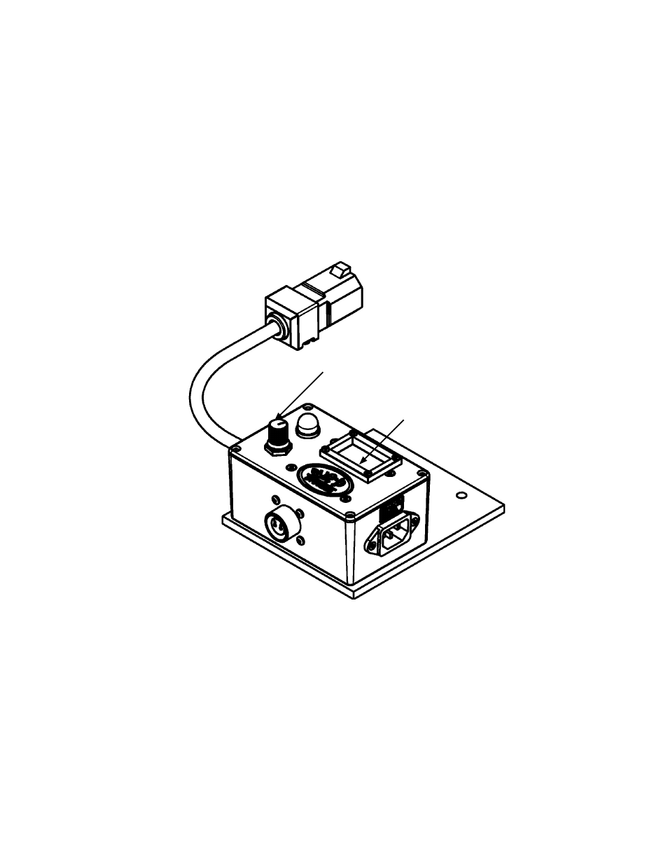
Now that limit switch is mounted, screw the amphenol end of the limit switch cable into the amphenol
connector on the Stepper Module. The Stepper Module is mounted to the BUG-O tractor, BUG-O trac-
tor is plugged into the power cable of Stepper Module. Input power is connected to Stepper Module. It
is time to test set-up.
Turn timer adjustment to display 3 seconds (3.0), this is an arbitrary value for this testing. Without turn-
ing your lathe or turning rolls on, manually trigger the limit switch, make sure to completely release the
limit switch (see “NOTE” below). The BUG-O should move until the relay completes the timed cycle,
then stops. Now, trigger the limit switch a second time, the BUG-O should move the same distance and
stop. Timer adjustment can now be set to desired time.
NOTE: If the limit switch is not completely released, the
timer will not reset. If not completely released activating
the limit switch will not result in the BUG-O moving.
Make certain that the limit switch mount will allow the
limit switch to completely reset. Revise the mounting or
adjust the limit so that the limit switch resets.
Timer Adjustment
Display