Wiring diagram / electrical component chart, Bug-987x stepper module / wiring diagram – BUG-O Systems BUG-9870 User Manual
Page 10
10
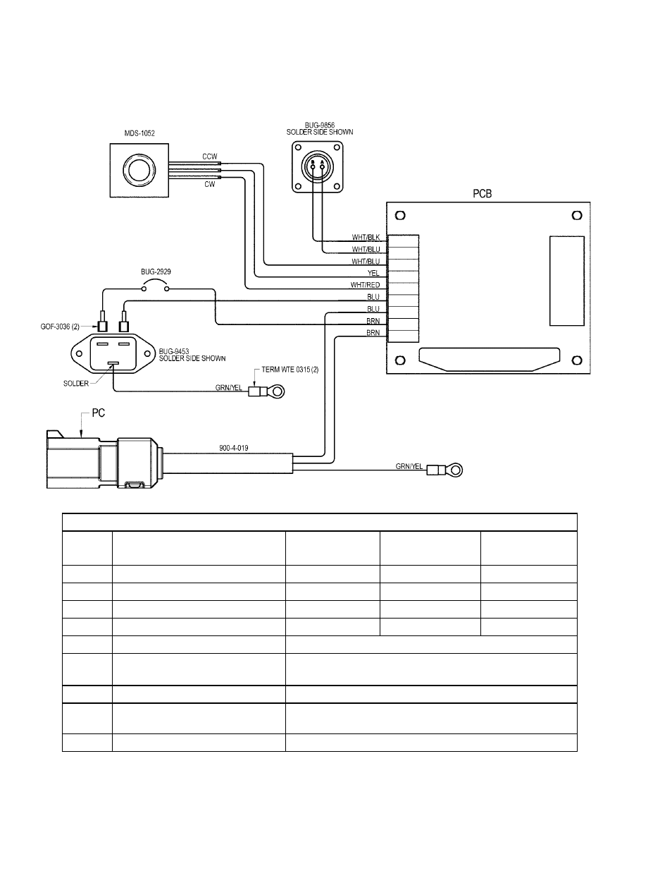
BUG-987X STEPPER MODULE / WIRING DIAGRAM
ELECTRICAL COMPONENT CHART
ITEM*
DESCRIPTION
BUG-9870 120
VAC
BUG-9872
240 VAC
BUG-9874
42 VAC
6
V-Lock Power Cord
BUG-9454
BUG-9454-240
BUG-9454-42
7
Receptacle
BUG-2847
BUG-9594
BUG-2847
25
Digital Stepper Module
PCB-1219
PCB-1219
PCB-1219-42
33
Voltage Label
BUG-9234
BUG-9233
BUG-9492
3
Circuit Breaker
BUG-2929
5
V-Lock Power Inlet
BUG-9453
BUG-9454
8
Panel Connector
BUG-9856
12
Limit Switch in BUG-9875
Stepper Module Switch Assembly
BUG-1417
19
Potentiometer
MDS-1052
* See Exploded View for Item Number relations