Setup – BUG-O Systems BUG-9870 User Manual
Page 6
6
SETUP
Mount Stepper module to the BUG-O tractor using two (2) ¼-20 x screws, hex head, socket head or
cap screws (not supplied), using the mounting holes on the BUG-O carriage.
Mount Limit Switch to work where a trip mechanism will actuate the limit switch with each revolution of
the work piece. “Trip” can be a screw head, flag, spot weld or any other item that will activate the limit
switch / BUG-O. Mounting brackets used to install the Limit Switch are of your own make or purchase
that is appropriate to the specific application.
Plug power cord of Stepper Module into main power supply.
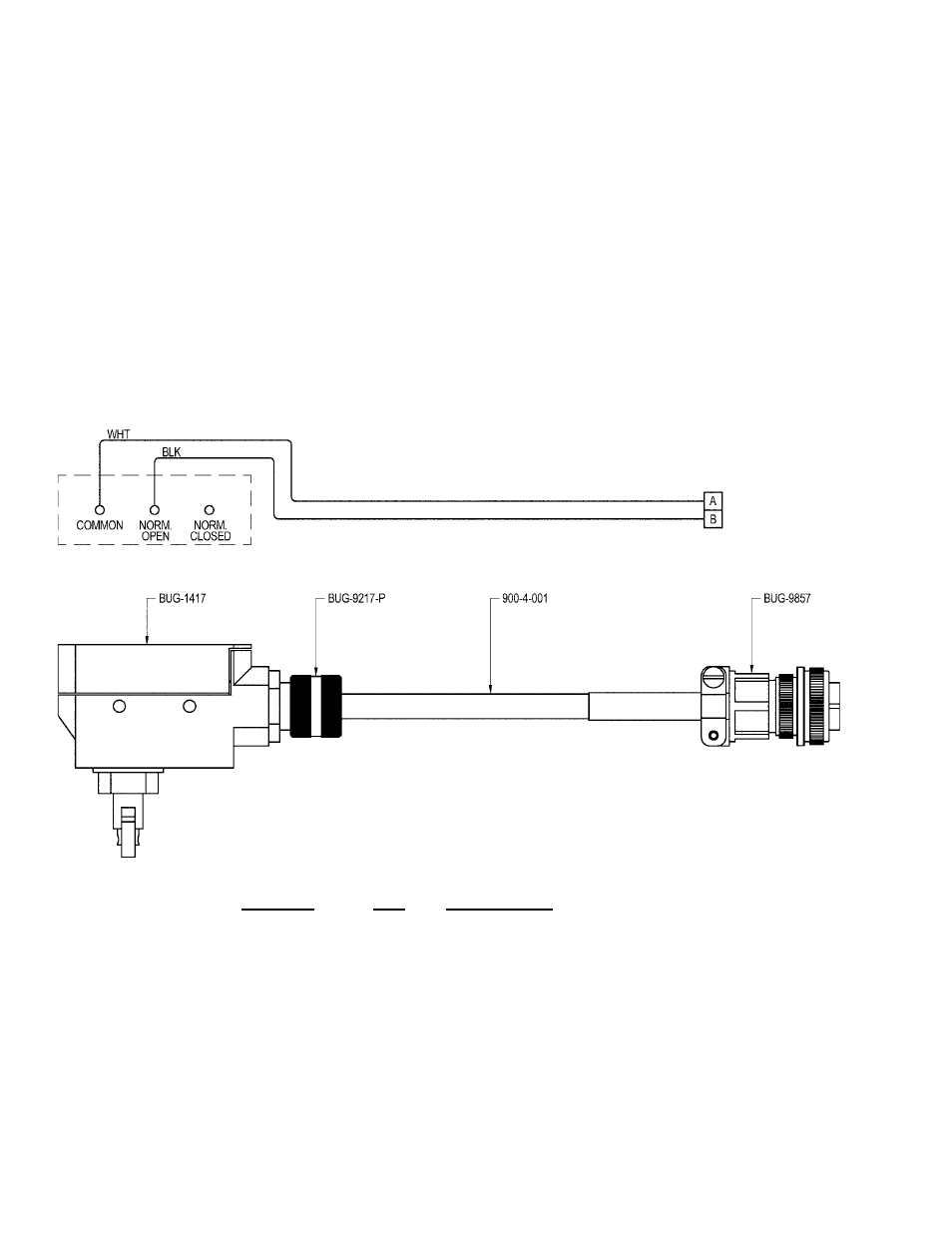
BUG-9875 STEPPER MODULE SWITCH ASSEMBLY / PARTS LIST / WIRING DIAGRAM
PART NO.
QTY
DESCRIPTION
900-4-001
96"
Power Cord, SJO 18/2-250,
300V
BUG-1417
1
Cross Roller Plunger Actuated
BUG-9217-P
1
Cord Grip
BUG-9857
1
Cable Connector, 2-7, M