BUG-O Systems SPB-3000 User Manual
Page 8
8
MACHINE COMPONENTS, CON’T
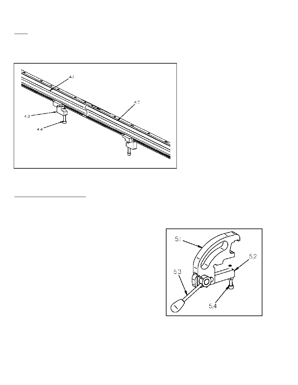
RAIL
The standard rail consists of two easily disconnected tip segments and two moveable end
clamps, as shown in Figure 6, and spans 2 m long. For longer bevel lengths, one-meter center
segments can be added between the tip segments.
4.1 Tip segment – left
4.2 Tip segment – right
4.3 End clamp
4.4 Clamp screw
RAIL ALIGNMENT CLAMP
Rail alignment clamps position and secure the rail against the work piece. Use the clamp lever,
shown in Figure 7, to press the rail against the work piece and minimize the effects due to out-of-flat
plate. Three rail alignment clamps are supplied with the standard SPB-3000. Rail alignment clamps
are adjusted during operation. At all times, two out of three rail alignment clamps should be
clamped.
5.1
Alignment clamp body
5.2
Alignment clamp arms
5.3
Alignment clamp lever
5.4
Adjusting screw
Adjusting screw (5.4) is used to correct for work piece thickness. Proper alignment clamp
operation requires a snug fit of work piece to alignment clamp. An alignment clamp can be moved
only when the lever (5.3) is in the up position. Figure 7 shows the lever in the down position.
Figure 6: Rail
Figure 7: Rail Alignment Clamp