Adjustable beam rails / arr-9045 / arr-9046, Assembly instructions – BUG-O Systems BEAM BUG III User Manual
Page 21
4
21
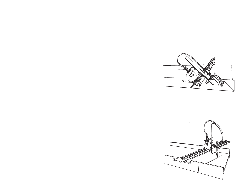
ADJUSTABLE BEAM RAILS
ARR-9045 / ARR-9046
The adjustable beam rail makes it possible to use the BEAM BUG III for miter
cutting in addition to straight cutting, beveling and coping. The adjustable
beam rail can be positioned for 0
0
- 45
0
cuts, in either direction on any beam
up to a 36" (915 mm) wide flange, [60" (1525 mm) with ARR-9046].
The adjustable beam rail is positioned on the work using two magnetic bars,
which fasten on each flange. Two stop plates hold the rail perpendicular to
the work for straight cutting. By loosening the eccentric clamp assemblies and
sliding the stop plates toward the center, the rail can be rotated to any angle
between 0
0
and 45
0
in either direction. The rail is locked in the appropriate
position, parallel to the layout line, by tightening the clamp assemblies.
A miter cut on the web is set up using the same eccentric clamps and sliding
either one of the magnetic mounting assemblies away from the other one. The
rail is then clamped in position, ready to cut, 0
0
-45
0
. Two knob screws with
ball ends enable you to “slide” the magnetic bar easily from one position to
the other, and may also be used to release the magnets from the workpiece.
The adjustable beam rail has a net weight of 42 lbs. (19 kg) and a shipping
weight of 75 lbs. (34 kg).
ARR-9046 adjustable beam rail has a net weight
of 65 lbs. (30 kg) and a shipping weight of 90 lbs.
(41 kg).
CAUTION:
Remove BEAM BUG III from rail
when releasing magnets or adjusting.
1. The BEAM BUG III is shipped in two boxes, open each box carefully:
A. The large box contains the machine, torch mount, torch, tips and
hose.
B. The smaller box contains the flange rail.
2. A BEAM RAIL is required for the BEAM BUG III to operate on. When
ordered with the
BEAM BUG III, the BEAM RAIL is shipped in a sepa-
rate box.
3. Install the Rack Assembly (G) on Flange Rail (B) [See Fig.1] in
appropriate hole for the flange size being cut, using
Fasteners (X) provided.
4. Remove small Screw (A) from torch end of Flange Rail (B).
5. Plug Power Cord (W) into appropriate power source. Pilot Light (Y)
will glow when power is on.
6. Lay machine on its back and carefully guide Flange Rail (B) through
Wheels (C) from top of machine (handle side) toward bottom. Throw
Vertical Travel Switch (E) “Down”, carefully engage Pinion (D) with
rack and feed rail through bottom set of
Wheels (F). When Flange Rail
(B) is approximately 12" (300 mm) past bottom of machine, stop rail travel,
and replace small
Screw (A) from [Step 4] and throw Vertical Travel
Switch (E) “Up”. Rail should stop automatically when screw contacts limit
switch.
7. Mount Swivel Torchholder Assembly (H) on Rack (G).
8. Install Right Angle Fittings (AA) on Torch (BB). Connect Check
Valves (CC) into Right Angle Fittings (AA). Connect Hoses (K) to Check
Valves (CC). Select and install proper Tip size (DD) in Torch (BB).
[See Tip Chart
(M) on side of machine].
9. Place Torch (BB) into Torchholder (H) and connect Supply Hoses (L)
and opposite end of
Hoses (K) to Manifold (S).
ASSEMBLY INSTRUCTIONS