Bronkhorst EL-FLOW Base 2010 User Manual
Page 3
9.17.060
3
4. Mount/install instrument properly:
Install the EL-FLOW Base Meter/Controller in the line, in accordance
with the direction of the FLOW arrow. The arrow for flow direction is
indicated on the body of the instrument.
Tighten the fittings according to the instructions of the supplier of the
fittings.
The use of Swagelok RS-type stainless steel adapters is recommended,
e.g. part number SS-400-1-4RS with Viton O-ring AS013 70°Sh.
Avoid installation in close proximity of mechanic vibration and/or heat sources.
5. Leak check:
Check the system for leaks before applying (fluid) pressure. Especially if toxic, explosive or other dangerous fluids
are used!
6. Electrical connection:
Electrical connections must be made with a standard
cable or according to the EL-FLOW Base hook-up diagram.
IP-40:
Please note that an EL-FLOW Base instrument is IP-40, implying that the electronics housing and electrical connection
do not offer any protection against moist environments.
7a. Analog/Local operation:
Connect the EL-FLOW Base to the power
supply/readout unit using a cable with 9-pin sub-D
connector.
Examples:
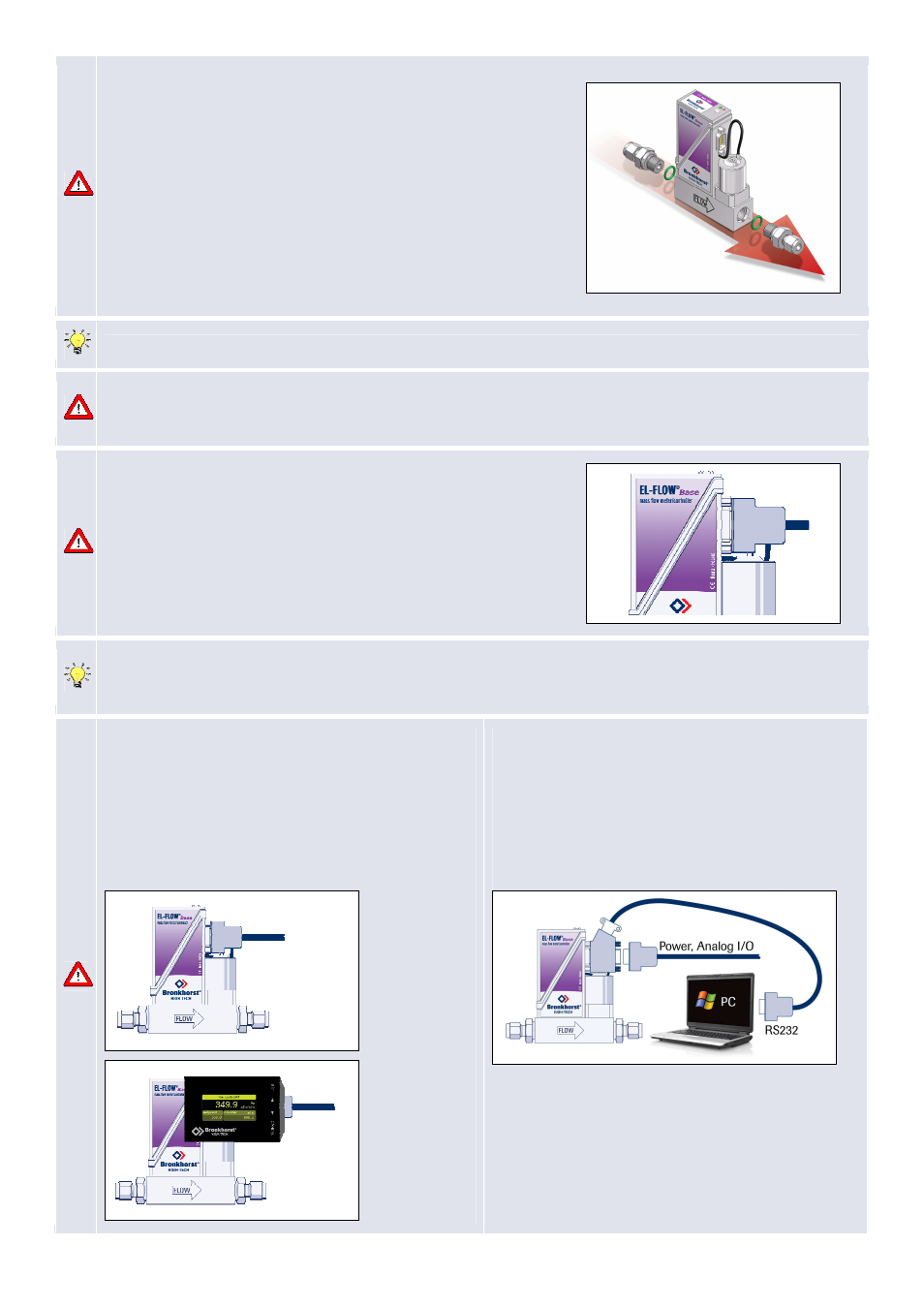
7b. BUS/digital operation:
For this procedure see description for RS232 operation
or Modbus. RS232 connection cable 7.03.366 enables
to use (free) Bronkhorst tooling programs for Windows.
Example:
Power:
+15...+24 Vdc
Analog input / output:
0…5Vdc / 0…10Vdc
0…20mA / 4…20mA
Power:
+15...+24 Vdc
Analog input / output:
0…5Vdc / 0…10Vdc
0…20mA / 4…20mA