Scope of this manual, Starting-up – Bronkhorst EL-FLOW Base 2010 User Manual
Page 2
9.17.060
2
SCOPE OF THIS MANUAL
EL-FLOW
Base
instruments are standard and straightforward Mass Flow Controllers. They provide accurate
measurement, fast response and stable control in common gas flow applications. The instruments operate on the
principle of thermal mass flow measurement in ranges starting from 0,2…10 ml
n
/min up to 1,4…70 l
n
/min air-
equivalent. They offer analog I/O-signals as well as digital RS232 communication and/or Modbus-RTU/RS485 as a
standard feature. EL-FLOW
Base
is a member of Bronkhorst’s most popular and field proven EL-FLOW
®
series.
This manual covers the short-form instructions for EL-FLOW
Base
mass flow instruments regarding:
- start-up
- mounting
- zeroing
- operation
This manual will help you start-up your EL-FLOW
Base
in only 10 steps. More detailed information can be found in
documents listed below:
- Instruction manual EL-FLOW
Base
series
(document nr. 9.17.061)
Consists information for basic and advanced operation, more detailed product information and instructions for
troubleshooting
- FlowPlot Manual
(document nr. 9.17.030)
- Hookup diagram EL-FLOW
Base
(document nr. 9.16.091)
These documents can be downloaded from the website: www.bronkhorst.com or can be sent by e-mail on request.
Starting-up
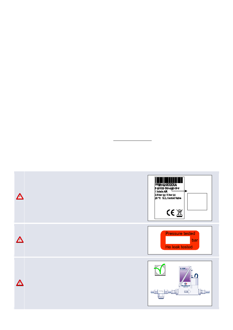
1. Check EL-FLOW Base properties:
Before installing your Mass Flow Meter/Controller it is important to read
the attached label and check:
- Flow rate
- Fluid to be measured
- Up- and downstream pressures
- Input/output signal
- Temperature
- Valve type
2. Check test-pressure:
Check the red-coloured sticker and make sure the test-pressure is in
accordance with normal safety factors for your application.
EL-FLOW Base instruments are tested up to the pressure indicated
on the red sticker.
3. Check if system piping is clean:
For reliable measurement always make sure the fluid stream is clean.
Use filters to assure a moisture-, oil- and particle-free gas stream.
Recommended pore-size: 5 µm.
If back flow can occur, a downstream filter and a check valve are
recommended too.
For high flow rates select a suitable filter size, to avoid
too high pressure drop.
10
OK
input/output
A – 0…5 Vdc
B – 0…10 Vdc
F – 0…20 mA
G – 4…20 mA