2 led functions, Led functions, Section 3.3.2 – Bronkhorst IQ+FLOW (from 01-07-2013) User Manual
Page 14: Section 3.3.3
Bronkhorst High-Tech B.V.
IQ+FLOW
9.17.045
14
LEDs
Time
Pushed
Indication
Green
Red
Off
Off
0 – 4 sec.
No action. Pressing a switch shortly by accident will not start any unwanted
reaction of the instrument.
Off
Normal
flash
0,2 sec on,
0,2 sec off
4 – 8 sec.
Restore factory settings
All parameter settings (except field bus settings) will be restored to situation of
final test at Bronkhorst production.
Normal
flash
0,2 sec on,
0,2 sec off
On
8 – 12 sec.
For FLOW-BUS only: install a free node-address on FLOW-BUS.
Normal
flash
0,2 sec on,
0,2 sec off
Normal
flash
0,2 sec on,
0,2 sec off
12 – 16 sec
Activate 'Configuration Mode'. The baud rate and bus type are set to 38k4 and
RS232 FLOW-BUS (Propar). The 'Configuration Mode' is recognized by the
green LED blinking 2 sec on, 0,1 sec off. The 'Configuration Mode' is
deactivated only after applying this micro-switch action again.
LED indications using micro-switch at power-up situation of an instrument
3.3.2
LED functions
The LEDs on top of the instrument can also be used for manual operation of some options. The green LED will indicate in what
mode the instrument is active. The red LED will indicate error/warning situations.
i
www
For details see “Manual interface: micro-switch and LEDs” in Operation Instructions Digital Instruments:
(document nr. 9.17.023, Chapter 11)
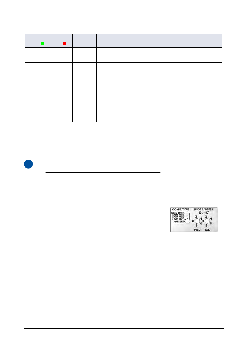
3.3.3
Rotary switch operation (multi-channel versions only)
The IQ
+
FLOW® multi-channel instruments are equipped with rotary switches for selection of communication type, baud rate and
node address.
Communication type switch
With the 'COMM. TYPE' switch the following communication types can be selected:
0. RS485 9k6: Modbus RTU protocol with baud rate 9600, EVEN parity
1. RS485 19k2: Modbus RTU protocol with baud rate 19200, EVEN parity
2. RS485 38k4: Modbus RTU protocol with baud rate 38400, EVEN partiy
3. RS232 38k4: FLOW-BUS protocol with baud rate 38400
4. RS232 115k2: FLOW-BUS protocol with baud rate 115200
Node address switches
With the two 'NODE ADDRESS' switches the node address of the instrument channels can be selected. The 'MSD' (Most Significant
Digit) sets the first digit (tens), the 'LSD' (Least Significant Digit) sets the second digit (units). The node address of channel 1 is set
with the switches, the channels 2 and 3 receive 'node address' + 1 and 'node address' + 2 respectively (e.g. MSD = 1 and LSD = 9
selects node 19 for channel 1, but also node 20 and 21 for channels 2 and 3).