0 operation, Table 1 status indicators – Broadata Communications Mini-DVI-AD Series User Manual
Page 14
Mini-DVI-AD User’s Manual
Miniature Multimode Fiber Optic DVI Transmission System
Broadata Technical Support, [email protected]
15
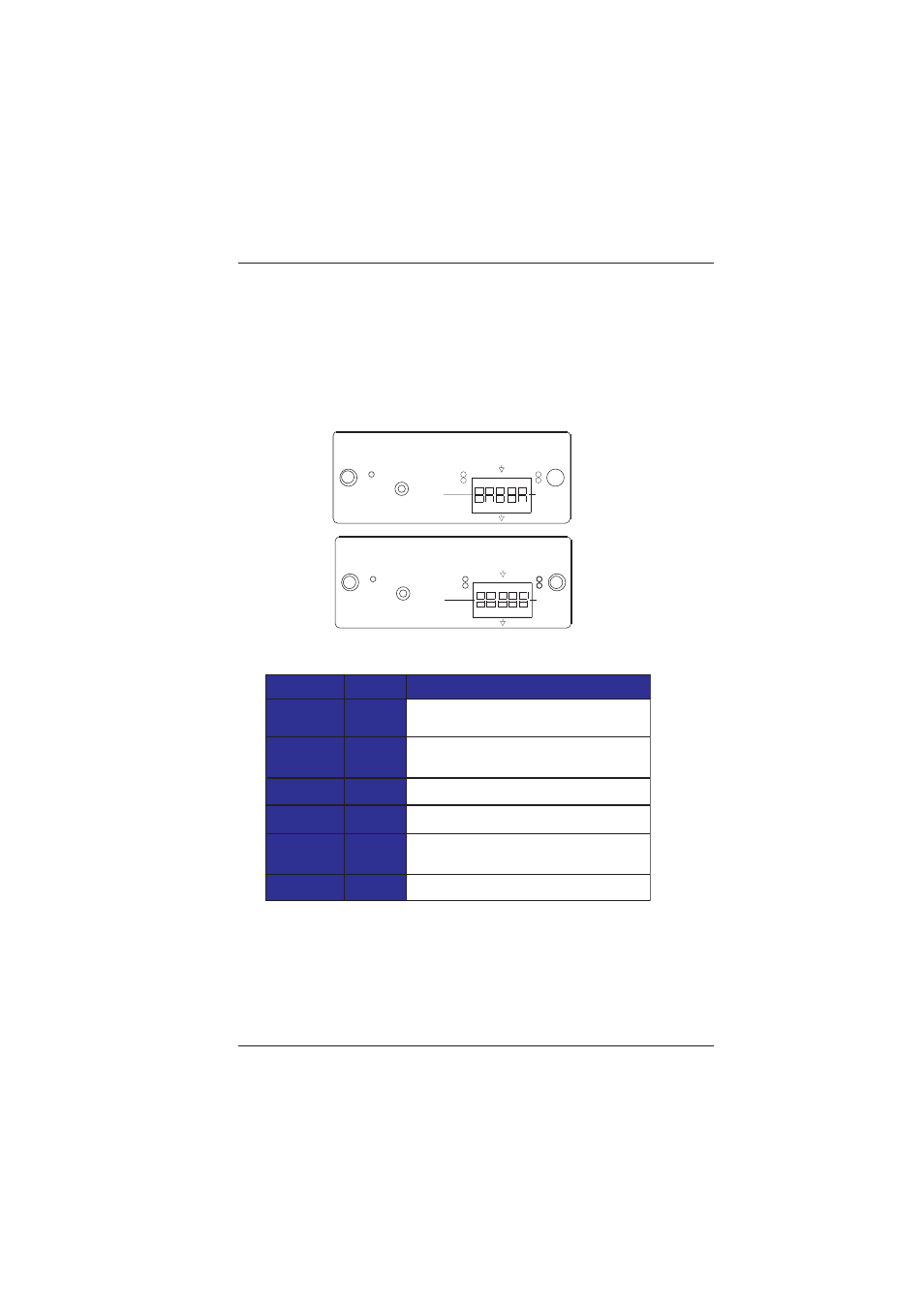
3.0 OPERATION
After the installation procedure is completed, the units are ready for
operation. To operate the BCI Mini-DVI-AD units, simply apply power
as indicated in the previous step. Note that the front panel link status
indicator, shown in Table 1, will be activated.
Table 1
Status Indicators
This GREEN LED indicates L/R-channel input
audio activity
This GREEN LED indicates L/R-channel output
audio activity
This GREEN LED indicates input data activity
This GREEN LED indicates output data activity
This GREEN LED indicates optical link and power
are present and established
The RED LED indicates that power is present
PWR
Power
Audio-IN
Audio-OUT
Data-IN
Data-OUT
Link
AUD(io) I(n)
AUD(io) O(ut)
DAT(a) I(n)
DAT(a) O(ut)
LINK
Label
Function
Description
O
1
2
1
2
I
Mini-DVI-AD-TX
DATA
D
AUDIO
IN
1
2
1
OUT
A
O
2
PWR
LINK
I
O
I
OUT
1
1
Mini-DVI-AD-RX
LINK
PWR
DATA
O
O
I
AUDIO
D
2
2
1
I
2
2
1
IN
I
O
A