2 receiver front and rear panels, Front, Rear – Broadata Communications LBC-HDBT User Manual
Page 6
LBC-HDBT User’s Manual
Link Bridge
TM
HDbaseT HDMI Transmission System
Broadata Technical Support, [email protected]
7
8.
Link LED: The yellow LED will illuminate when both the input
and output signals are connected.
9.
CAT5e/6 Out: Connect to the reciever unit with a Single CAT5e/6
cable for tranmission of all data signals.
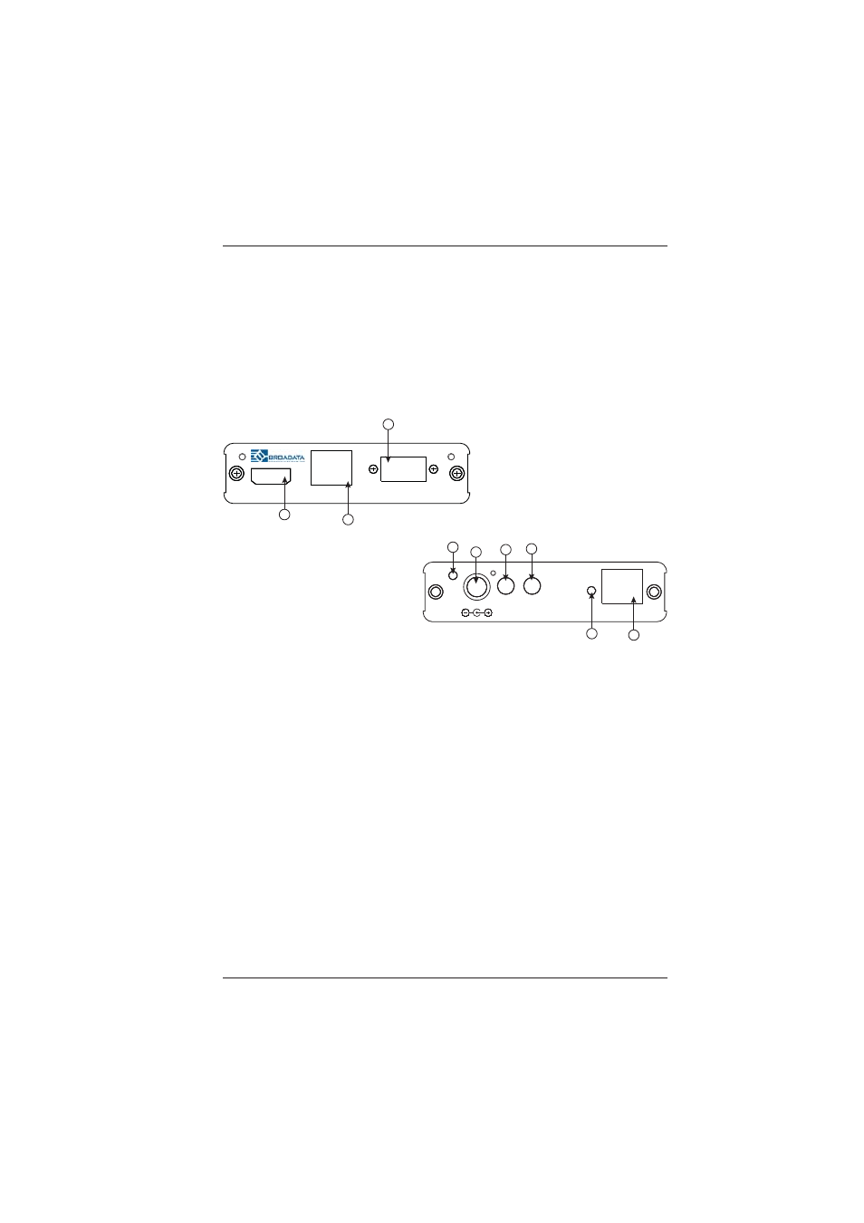
2.2 Receiver Front and Rear Panels
1.
HDMI Out: Connect to a HDMI equipped TV/monitor for display
of the HDMI input source signal.
2.
LAN: Connect to a PC or Laptop to the Internet or network
connection.
3.
RS-232 Out: Connect to the device that is to be controlled (via
D-Sub 9 pin female cable) by RS-232 commands.
4.
Power LED: This blue LED will illuminate when the device is
connected to a power supply.
5.
DC 24V: Plug the 24 V DC power supply into the unit and connect
the adaptor to an AC outlet. Only one side of power needs to be
connected to activate both transmitter and receiver.
6.
IR 2 Blaster: Connect to the supplied IR blaster cable for IR
signal transmission. Place the IR blaster in direct line of sight
of the equipment to be controlled.
HDMI-OUT
ETHERNET
RS-232
LBC-HDBT-RX
1
2
3
Front
LINK
HDBT
OUT IN
IR
PWR
+24VDC
4
5
6
7
8
9
Rear