Assembly, Figure 4 figure 5 figure 6 – Brinly DT-402 BH Dethatcher User Manual
Page 6
1008565EN-B
6.
ASSEMBLY
================================================================================================
4
8
22
16
16
22
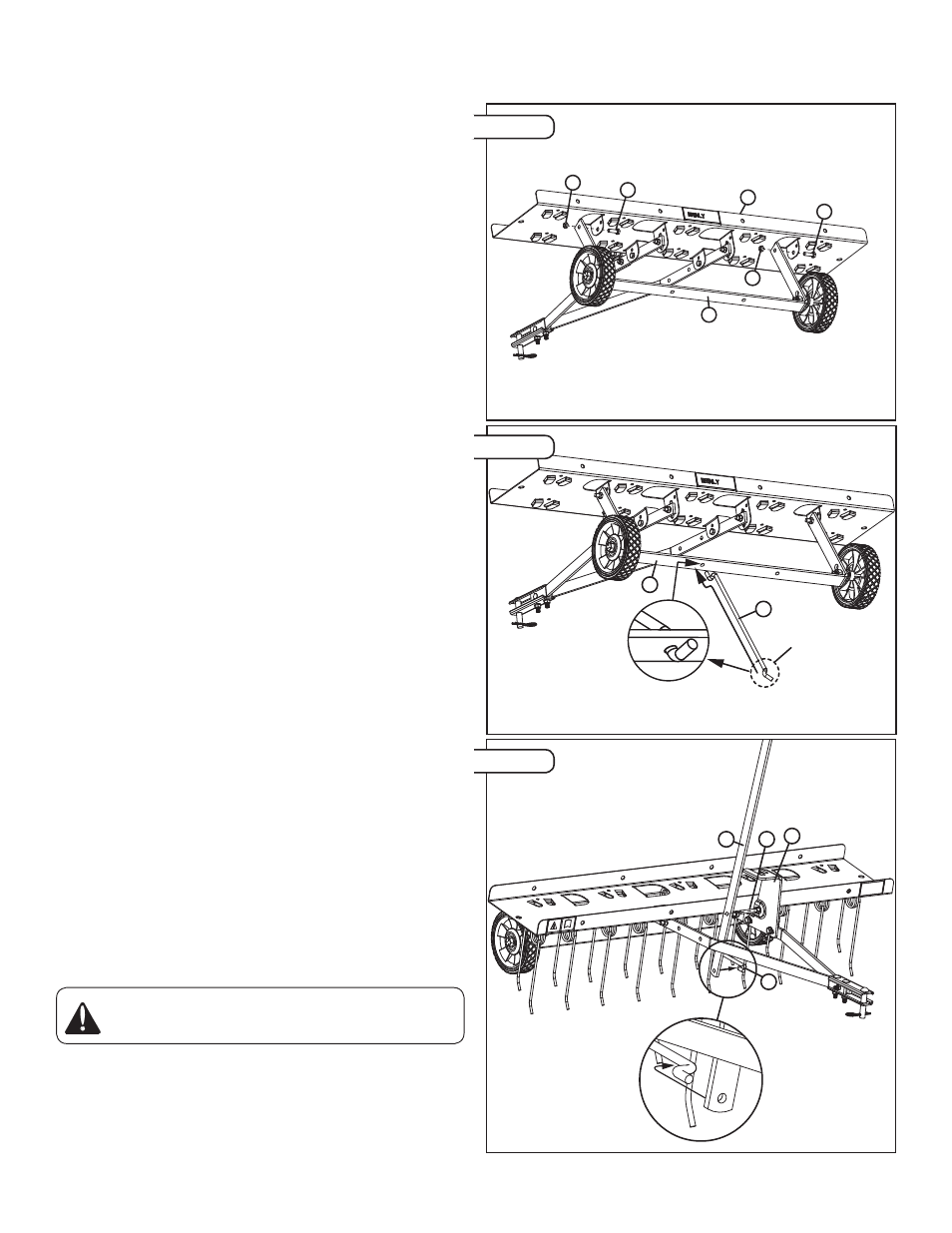
NOTE: Tines and Safety
Wires not shown.
4)
Attach the Wheel Bracket (4) to the Tray (8) using the hardware in
Panel 4 as shown in Figure 4.
NOTE: Tighten the nuts assembled in this step to allow the
Wheel Bracket Assembly to rotate with minimum "side to
side" looseness.
5) Starting with the 90 degree bent end, assemble the Control Rod
(5) into the left hole on the Wheel Bracket (4) as shown in Figure
5. Feed Control Rod (5) through hole until opposite end engages
with Wheel Bracket (4).
NOTE: The Control Rod Must Be orientated as shown in
Figure 5 after assembly.
6A) Orientate Handle (3) between Towbars. Attach the end of the
Control Rod with the 90 degree bends to the Handle (3) as shown
in Figure 6.
6B) Assemble the handle onto the Bolt (12) that runs through the
Lift Lock (2) as shown in Figure 6. Orientate Handle so that it is
engaged with one of the Tine height settings on the Lift Lock (2).
Figure 7 shows the handle in set to dethatch mode.
CAUTION: Avoid Injury! Movement and Tine height
adjustment of Handle, Lift Lock, and Spring can be a
pinch point. Take care when working in this area.
4
5
NOTE: Tines and Safety
Wires not shown.
After assembly,
this end should
be engaged
with Wheel
Bracket (4).
5
3
12
2
Figure 4
Figure 5
Figure 6