Equipment and functions, Front panel functions, Figure 13 – Diversified Ceramics DISPLACEMENT FOLLOWER 5100 User Manual
Page 15
Displacement Follower User’s Manual
Version 1.4, April 19, 2004
IM1008
Page 13
Equipment and Functions
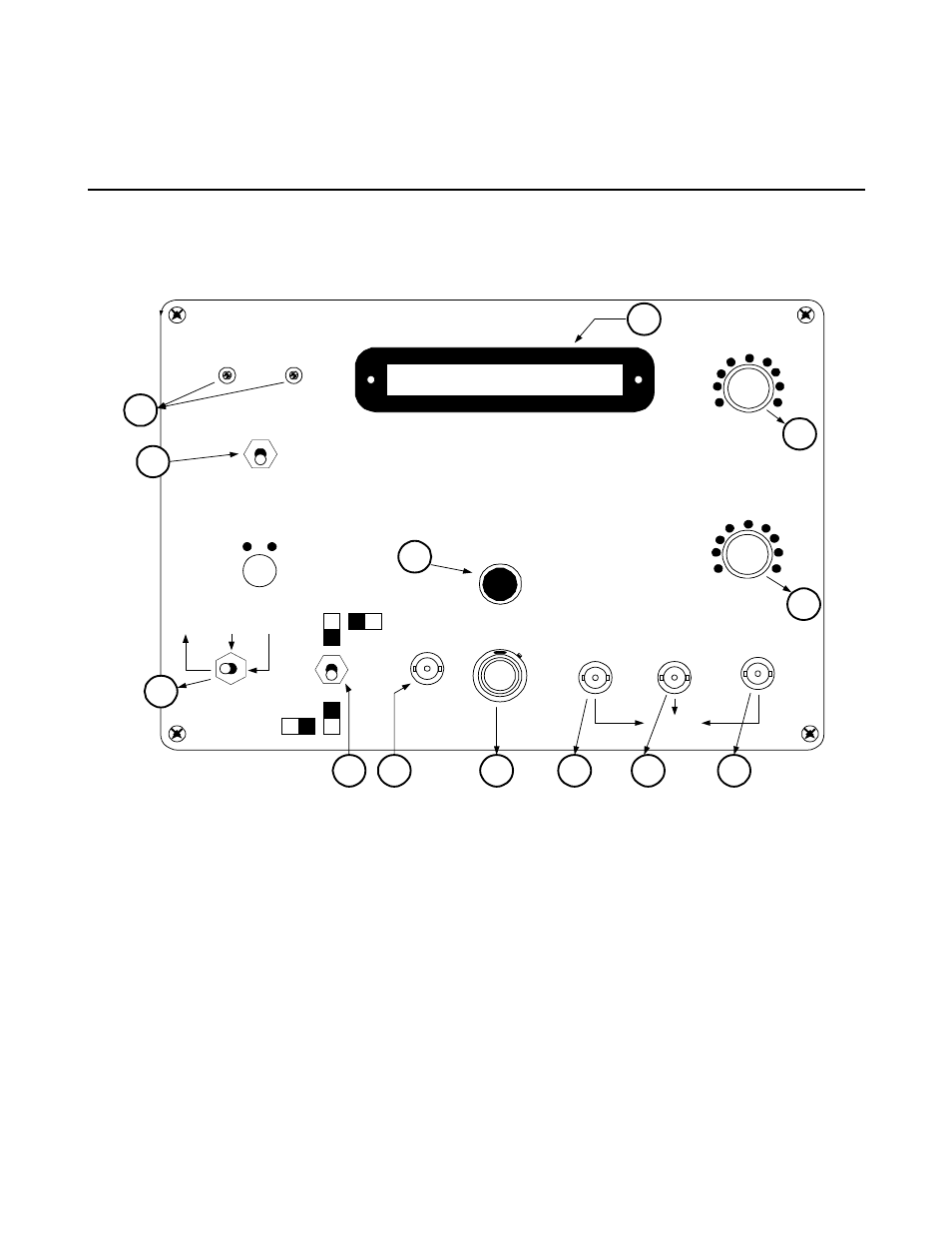
Front Panel Functions
Figure 13
1
Power Indicator Indicates that the system is on. The power switch on the rear panel turns the system on and off. To
avoid the possibility of electric shock, connect the control unit to the tracking head using the interconnecting
cable before you turn the system on.
2
Lock-On Adjustment Adjusts an internal reference voltage in the servo loop to allow the system to track targets of
varying contrast ratios and of varying illumination intensities. When viewing the dark portion of the target, adjust the
lock-on potentiometer for a light reading of –20. See Operating Procedures 16 on page .
3
Light/Operate Switch Operate position: allows the meter and displacement output to exhibit the position of the
target under study. Light Level position: allows the meter to read the amount of light on the aperture in the photo tube.
The unit will not track a target while reading light levels.
Velocity
Time (msec)
Acceleration
3
1
10
.3
30
100
.1
300
.03
3
1
10
.3
30
100
.1
300
.03
A
B
O P E R A T E
LIGHT LEVEL
CALIBRATE
O R T H O
INPUT
GAIN
NORMAL LT SERVO
DISPLACEMENT VELOCITY ACCELERATION
O U T P U T
10KHZ
100HZ
Filter
50KHZ
Level Meter
Diversified Optronix
Single Axis Displacement
Follower Controller
M o d e l 5 1 0 0
P O W E R
O N
2
12
11
10
9
8
7
6
5
4
1
3
13
LOCK