Usb interface – Bematech KC-1800 User Manual
Page 18
User’s Manual
18
Signal pin
Signal
1
NC
2
DATA+
3
DATA -
4
GND
2 1
Figure 17
3 4
Signal pin
10
11
12
13
14,15,18,36
16
17
19-30
31
32
33
34
35
Associated
return pin
28
29
30
Signal
/ACK
BUSY
PE
OL OUT
NC
GND
Frame
GND
/INIT
/ERROR
GND
NC
PULLUP
Description
This pulse is active low and indicates that data
sent to the printer has been received. The pulse
width must be larger that 10us.
When high, indicates that the printer cannot
receive data.
Becomes high in case of:
1 – Paper end.
0 – Near paper end.
On line Out. When high, indicates operation in
remote mode. When low, indicates operation in
local mode.
Not connected.
Circuit ground.
Frame ground.
Circuit ground.
When low initializes the printer. It may be larger
than 50us.
Paper absence.
Circuit ground.
Not connected.
“Pulled Up” to +5V
Direction
OUT
OUT
OUT
OUT
IN
OUT
OUT
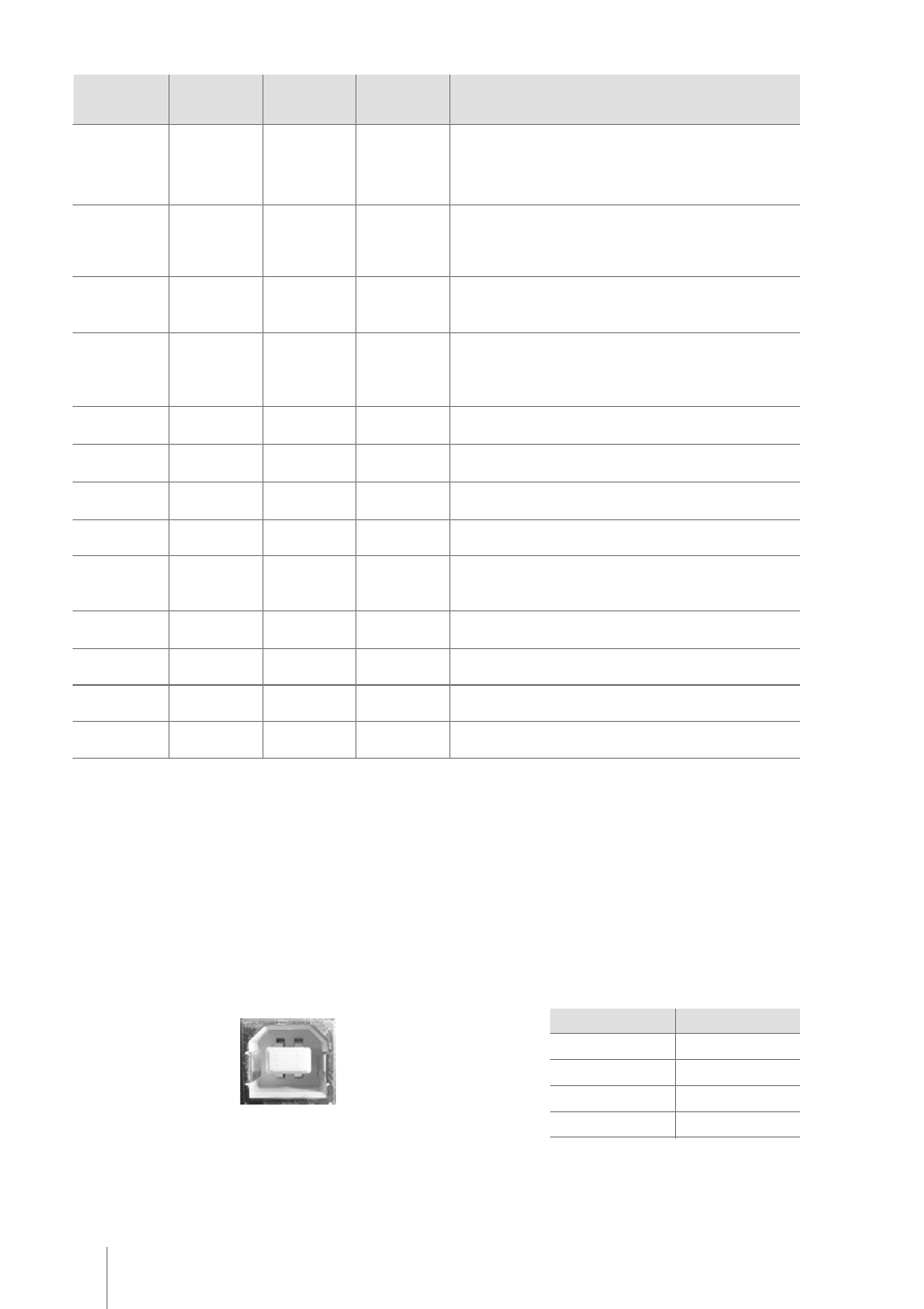
USB Interface
The USB interface is compatible with the Universal Serial Bus Specification 1.1. It is a 12 Mbps serial channel using
the Bulk mode with a “B” receptacle as show below. The USB cable must have in one side an “A” plug to connect
in the host, and in the other side an “B” plug to connect in the printer. The printer is self-powered and does not draw
power from the standard type B USB interface cable.
Type “B” Receptacle
Using the USB interface, the printer can be connected to the host even if both parts are powered. The first time you
connect the printer to the host, the operation system will ask for the printer driver. Please download the latest printer
driver from our website (www.bematech.com). For more details please contact your dealer.