3 power supply, 1 power connection – BECKHOFF EP9128 User Manual
Page 34
Mounting and cabling
ZK10909191
0001
0002
0005
0010
0020
0030
0040
0050
0100
0150
Length
0.17 m
0.26 m
0.5 m
1.0 m
2.0 m
3.0 m
4.0 m
5.0 m
10 m
15 m
ZK10909191
0200
0250
0300
0350
0400
0450
0500
Length
20 m
25 m
30 m
35 m
40 m
45 m
50 m
4.3
Power supply
4.3.1
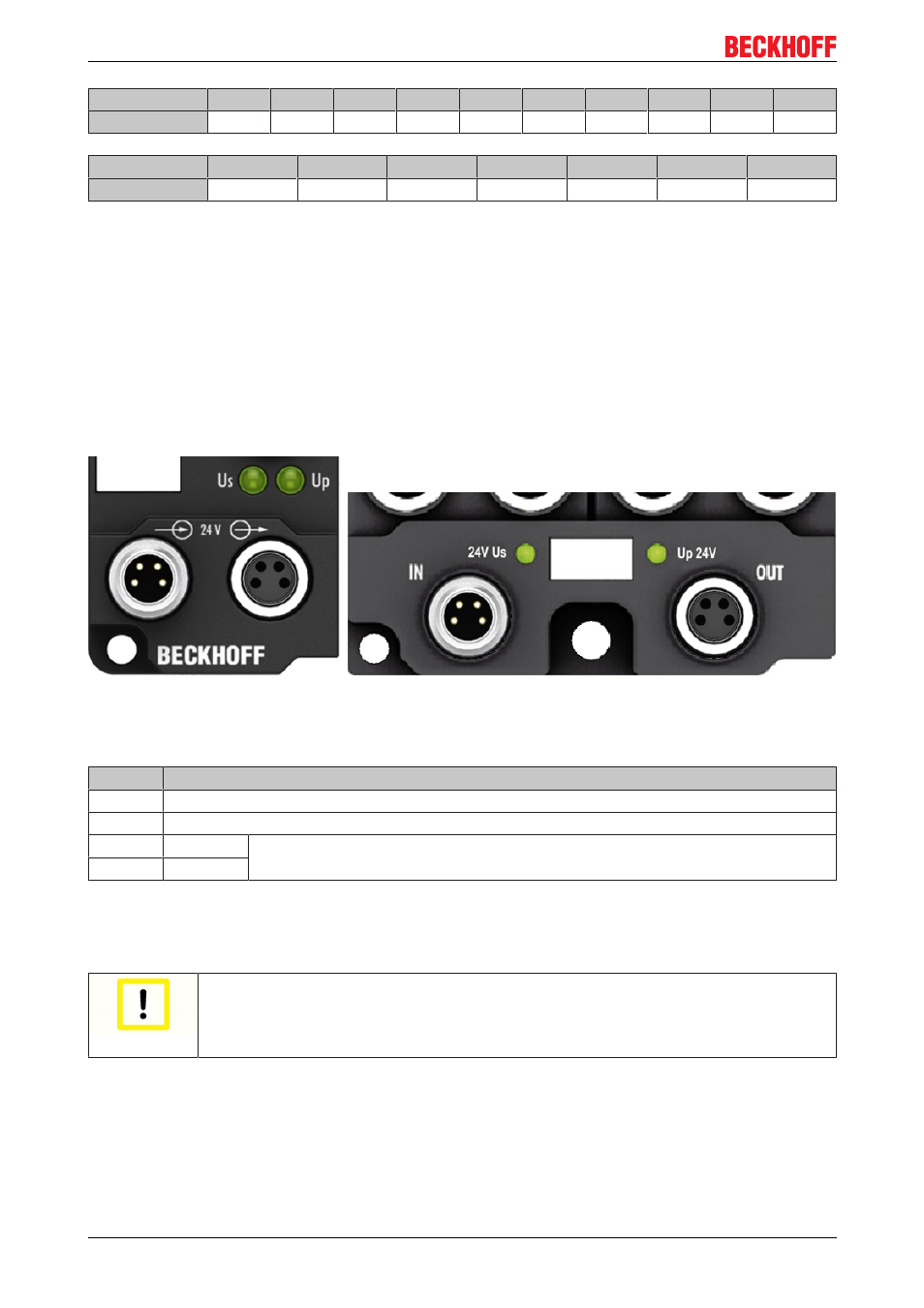
Power Connection
The feeding and forwarding of supply voltages is done via two M8 connectors at the bottom end of the
modules:
• IN: left M8 connector for feeding the supply voltages
• OUT: right M8 connector for forwarding the supply voltages
Fig. 43: EtherCAT Box, Connectors for power supply
Table 1: PIN assignment
Pin
Voltage
1
Control voltage Us, +24 V
DC
2
Auxiliary voltage Up, +24 V
DC
3
GNDs*
*) may be connected internally to each other depending on the module: see specific
module descriptions
4
GNDp*
The pins M8 connectors carry a maximum current of 4 A.
Two LEDs display the status of the supply voltages.
Attention
Don't confuse the power connectors with the EtherCAT connectors!
Never connect the power cables (M8, 24 V
DC
) with the green marked EtherCAT sockets of
the EtherCAT Box Modules! This can damage the modules!
Control voltage Us: 24 V
DC
Power is supplied to the fieldbus, the processor logic, the inputs and the sensors from the 24 V
DC
control
voltage Us. The control voltage is electrically isolated from the fieldbus circuitry.
EP9128
34
Version 2.1.0