Terminal configuration – BECKHOFF KL5121 User Manual
Page 7
Terminal configuration
KL5121
7
Terminal configuration
Each terminal channel is mapped in the bus coupler. The terminal’s data is
mapped differently in the bus coupler’s memory depending on the type of
the bus coupler and on the set mapping configuration (eg.Motorola / Intel
format, word alignment,...).
In contrast to analogue input and output terminals, the KL5121 always also
maps the control and status byte, independently of the supervising fieldbus
system.
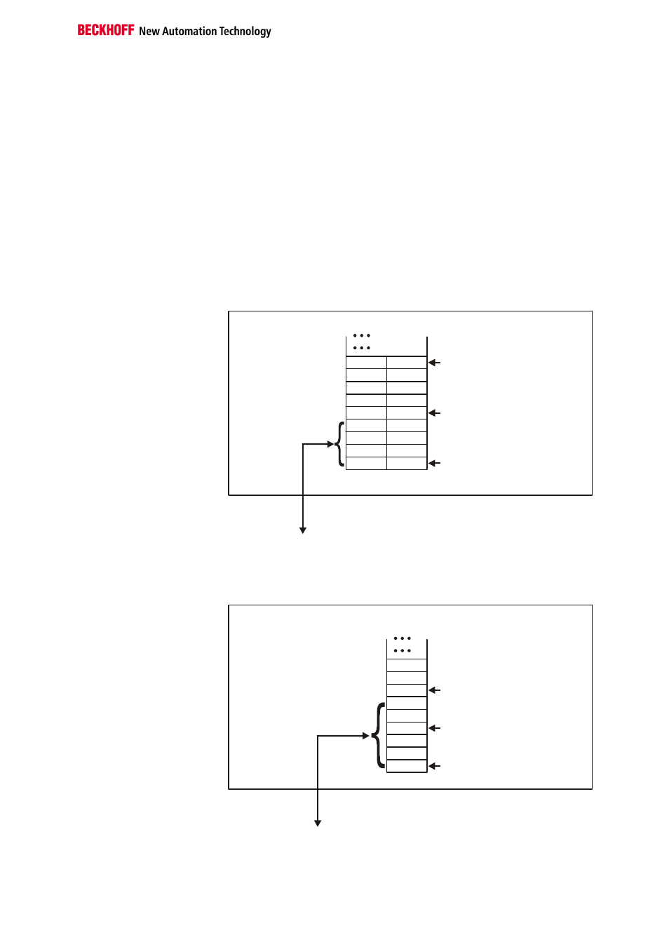
Beckhoff Lightbus
Coupler BK2000
In the case of the Beckhoff Lightbus coupler BK2000, the control /status
byte is always mapped besides the data bytes. It is always in the low byte
at the offset address of the terminal channel.
0
Offset Terminal1 Channel1 = 0
Offset Terminal2 Channel1 = 4
KL5121
Offset Terminal2 Channel2 = 8
User data allocation depending
on mapping
K-Bus
Beckhoff-Lightbus
bus coupler
BK2000
To the bus terminal
L
H
C/S - 0
D0 - 0
D0 - 1
D1 - 0
D1 - 1
C/S - 1
C/S
C/S
Data L
Data H
Data H Data L
C/S
The terminal is
mapped in the
bus coupler.
Profibus Coupler BK3000
In the BK3000 Profibus coupler, the KL5121 is always mapped with 6 bytes
of input data and 6 bytes of output data.
Offset Terminal1 Channel1 = 0
Offset Terminal1 Channel2 = 3
Offset Terminal2 Channel1 = 6
KL 5121 Channel1
KL 5121 Channel 2
The control-/status byte
must be inserted for
parameterization.
K-Bus
Profibus bus coupler
BK3000
To the bus terminal
Data H
Data L
D1 - 0
D0 - 0
D0 - 1
D1 - 1
C/S - 0
C/S
C/S - 1
0
The terminal is
mapped in the
bus coupler.