Register communication kl3351 – BECKHOFF KL3351 User Manual
Page 12
Register description
12
KL3351
The linearisation equation is activated by way of R32.
R35: Reserved
R36: Reserved
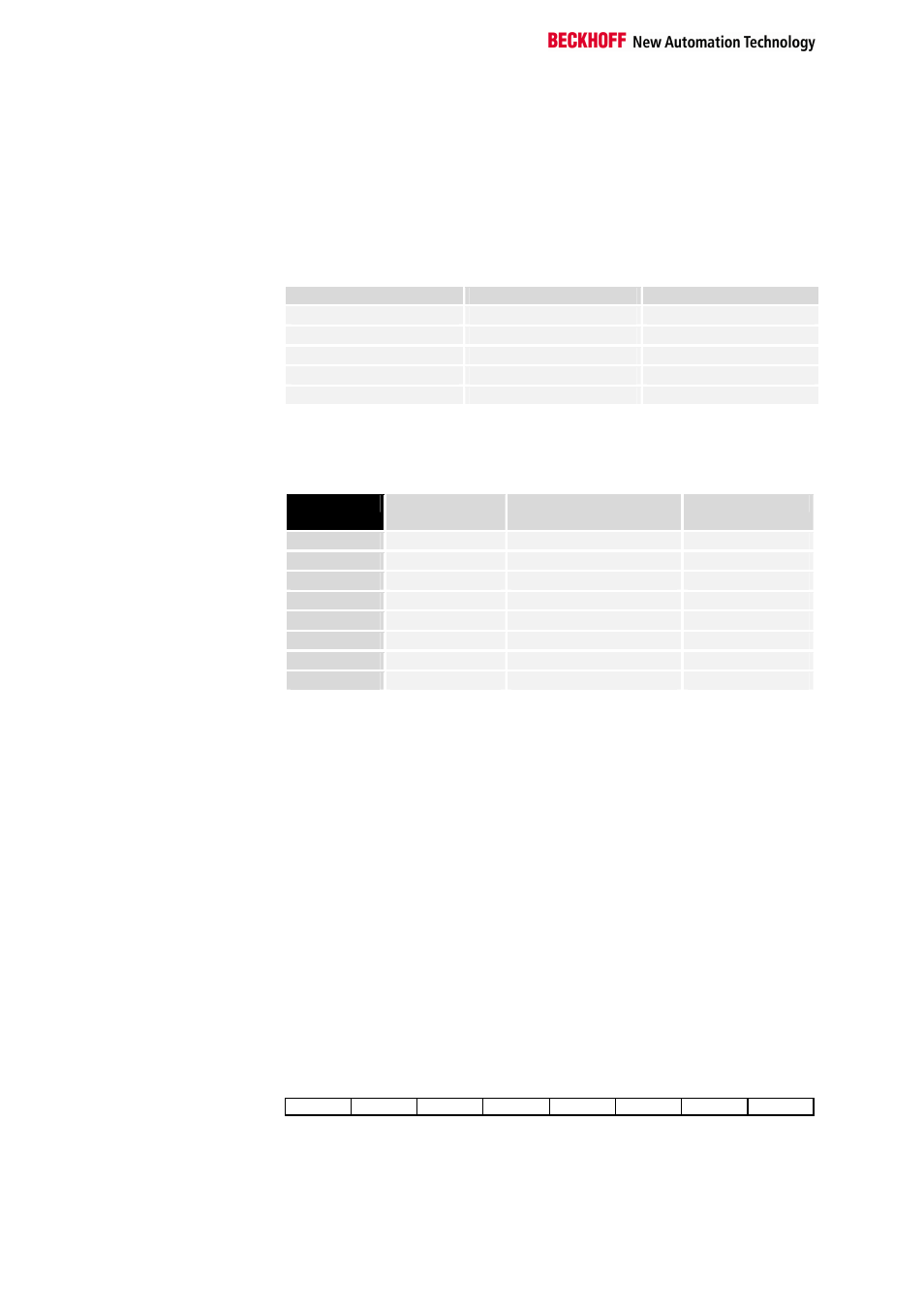
R37: Filter constant
[0x0000]
The filter constant is taken over after a power on RESET by the terminal.
Filter constants:
First notch [Hz]
Conversion time [ms]
0x0000
25
250
0x50
100
65
0xA0
50
125
0x140
25
250
0x280
12.5
500
R38: Gain setting [0x0010]
Various amplification factors are set with this register, permitting different
measurement resolutions.
R38
Gain
U
D
[µV]/Digit
U
ref
[mV]/Digit
0x0000
1
8
0x0004
2
4
0x0008
4
2
0x000C
8
1
0x0010
16
0.5
Default
0x0014
32
0.25
0x0018
64
0.125
Register communication KL3351
Register access via
process data transfer
Bit 7=1: register mode
When bit 7 of the control byte is set, the first two bytes of the user data are
not used for process data transfer, but are written into or read out of the
terminal’s register.
Bit 6=0: read
Bit 6=1: write
In bit 6 of the control byte, you define whether a register is to be read or
written. When bit 6 is not set, a register is read without modification. The
value can be taken from the input process image.
When bit 6 is set, the user data is written into a register. The operation is
concluded as soon as the status byte in the input process image has
supplied an acknowledgement (see examples).
Bits 0 to 5: address
The address of the register to be addressed is entered in bits 0 to 5 of the
control byte.
Control byte in the
register mode
MSB
REG=1
W/R
A5
A4
A3
A2
A1
A0
REG = 0 : Process data transfer
REG = 1 : Access to register structure
W/R = 0 : Read register
W/R = 1 : Write register
A5..A0 = Register address
A total of 64 registers can be addressed with the addresses A5....A0.