Control and status byte – BECKHOFF KL3311 User Manual
Page 16
Register Description
14
KL3311, KL3312, KL3314 and KL3302
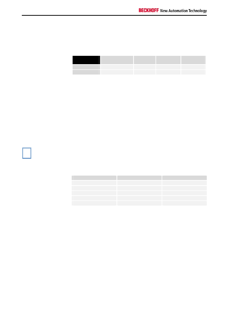
If the Siemens output format is selected, the lowest three bits are used to
assess the status. The process data is represented in bits 3 to 15, with bit
15 representing the sign bit. Scaling of the measurement reading according
to the Siemens standard has to be done via user scaling.
Measured
value
Bit 15 ... 3
Bit 2
X
Bit 1
Error
Bit 0
Overflow
out of range
0
0
1
in range
Process data
0
0
0
R33: User scaling - offset (B_w)
16 bit signed integer
This register contains the offset of the user straight-line equation (1.7). The
straight-line equation is activated via register R32.
R34: User scaling - gain (A_w)
16 bits signed integer* 2
-8
This register contains the scale factor of the user straight-line equation (1.7)
The straight-line equation is activated via register R32.
R35 and R36: reserved
R37: Filter constant
[0x0000]
i
Note
This documentation applies to all terminals from software version 3x. The
version number can be found within the serial number on the right-hand
side face of the terminal: xxxx3xxx
Example: 52983A2A
⇒ The firmware version is 3A.
Filter constants:
First notch [Hz]
Conversion time [ms]
0x0000
25
250
0x50
100
65
0xA0
50
125
0x140
25
250
0x280
12.5
500
Control and Status byte
Control byte for process
data exchange
The control byte is transmitted from the controller to the terminal. The
control byte is not used for KL331x and KL3302.
Status byte for process
data exchange
The status byte is transmitted from the terminal to the controller. The status
byte contains various status bits for the analog input channel:
status byte:
Bit 7 = 0
bin
Bit 6 = 1
bin
: ERROR - general error bit
Bit 5 to bit 2: reserved
Bit 1 = 1
bin
: Over range
Bit 0= 1
bin
: Under range
Compensation
The terminals are compensated when delivered.
In order to compensate tolerances of the external components, gain and
offset registers for compensating the thermocouple voltage are
implemented for each channel, i.e. R17 (thermocouple voltage offset) and
R18 (thermocouple voltage gain). For compensating the reference point
temperature (temperature at the transition between the thermocouple and