BECKHOFF KL3064 User Manual
Page 9
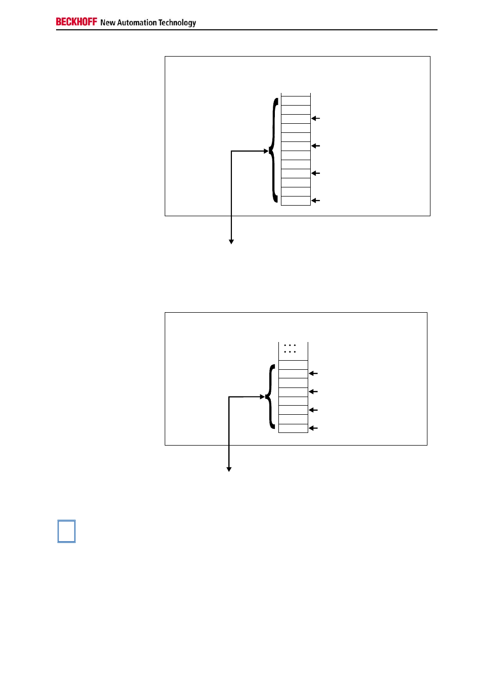
Terminal
configuration
KL3064
9
Offset Terminal1 Channel1 = 0
Offset Terminal1 Channel2 = 3
Offset Terminal1 Channel3 = 6
Offset Terminal1 Channel3 = 9
KL3064 Channel1
KL3064 Channel2
KL3064 Channel 3
KL3064 Channel 4
The control/staus byte
must be inserted for
parameterization.
K-Bus
Profibus bus coupler
BK3000
To the bus terminal
D1 - 0
D1 - 2
D0 - 2
D1 - 3
D0 - 3
D0 - 0
D0 - 1
D1 - 1
C/S - 0
C/S - 2
C/S - 3
C/S - 1
0
The terminal is
mapped in the
bus coupler
Interbus Coupler BK4000
By default, the Interbus coupler BK4000 maps the KL3064 with 8 bytes of
input data (2 bytes of user data per channel). Parametrization via the field
bus is not possible. The KS2000 software is required for configuration if
use is to be made of the control /status byte.
Offset Terminal1 Channel1 = 0
Offset Termianl1 Channel3 = 4
Offset Terminal1 Channel2 = 2
Offset Terminal1 Channel4 = 6
The control/status byte
must be inserted for
parameterization (KS2000).
K-Bus
Interbus bus coupler
BK4000
To the bus terminal
D0 - 1
D0 - 2
D0 - 3
D0 - 0
D1 - 0
D1 - 2
D1 - 3
D1 - 1
0
The terminal is
mapped in the
bus coupler
Other bus couplers and
further information
You will find further information on the mapping configuration of bus cou-
plers in the annex of the respective bus coupler manual under the heading
of "Configuration of masters".
i
Note
The annex contains an overview of the possible mapping configurations
depending on the adjustable parameters.
Parametrization with the
KS2000 software
Parametrization operations can be carried out independantly of the field
bus system using the Beckhoff KS2000 configuration software via the se-
rial configuration interface in the bus coupler.