Technical / plc data – BECKHOFF BC8000 User Manual
Page 13
Basic information
BC8000
13
Technical / PLC Data
The electrical data of the RS485 bus terminal controller are presented in
this chapter. The bus terminal controller is set to 19,200 baud data rate.
Addresses from 0 to 99 are selectable via two address selectors on the
coupler. The following table gives an overview of all the data:
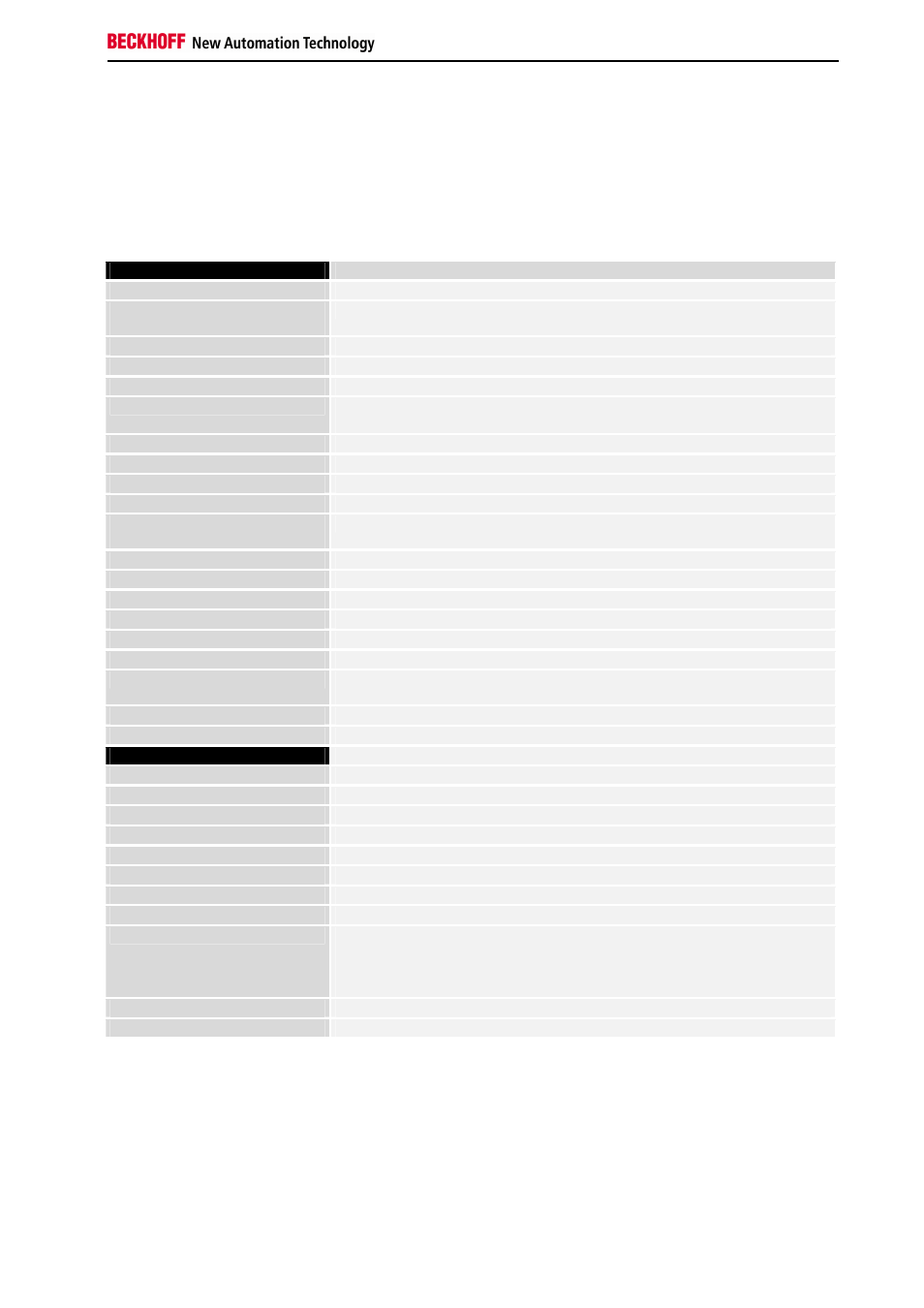
Technical data
BC8000
Number of bus terminals
64
Digital
peripheral signals
256 inputs and outputs
Analogue peripheral signals
128 inputs and outputs
Peripheral bytes
512 inputs and 512 outputs
Electrical power supply
24 V (- 15% / +20%) EN 61131
Input current
70 mA + (total K bus current)/4
500 mA max.
Power-on surge
2.5 x steady operating current
K-bus output current
1750 mA max.
Connector
1 x D-sub plug, 9-pin
Voltage of the power contact
24 V DC / AC
Power contacts current
drawn
10 A
Voltage stability
500 Veff (power contact / supply voltage)
Typical weight
170 g
Operating temperature
0°C ... +55°C
Storage temperature
-25°C ... +85°C
Relative humidity
95% without dew formation
Vibration/shock stability
according to IEC 68-2-6 / IEC 68-2-27
EMC immunity, burst / ESD
according to EN 61000-4-4 / EN 61000-4-2, limit values in accordance with
EN 50082-2
Installation location
arbitrary
Protection class
IP20
PLC data
Programmability
via programming interface or RS485 interface (TwinCAT BC/TwinCAT)
Program size
approx. 3000 PLC statements
Program memory
32 kbytes / 96 kbytes
Data storage
32 kbytes / 64 kbytes
Remanent flags
512 bytes
Runtime system
1 PLC task
PLC cycle time
approx. 3 ms for 1000 instructions (including K-bus I/O cycle)
Programming languages
IL, LD, FBD, SFC, ST
Station addresses
Selectable to 99 via DIP switch
0: reserved
1 – 98: programming mode
99: interface available for the PLC program
Interface
RS485
Baud rate
19,200 baud, 8 data bits, even parity, one stop bit
Current consumption on the
K-bus
For operation of the K-bus electronics, the bus terminals require energy
from the K-bus that is supplied by the bus coupler. Refer to the catalog or
the corresponding data sheets of the bus terminals for details of the K-bus
current consumption. In doing so, pay attention to the maximum output
current of the bus coupler that is available for powering the bus terminals.
Using a special power supply terminal (KL9400), power can be fed back
into the K-bus at any chosen point. If you wish to use a power supply
terminal, please contact Beckhoff’s technical support.