BECKHOFF BK4000 User Manual
Page 14
Basic information
14
BK4000
These assignments distinguish four groups:
Function type of the channel
Assignment level
1.
Analog outputs
byte-wise assignment
2.
Digital outputs
bit-wise assignment
3.
Analog inputs
byte-wise assignment
4
Digital inputs
bit-wise assignment
Analog inputs/outputs are representative of other complex multi-byte signal
bus terminals. The byte length of these terminals can be adjusted with the
KS2000 software.
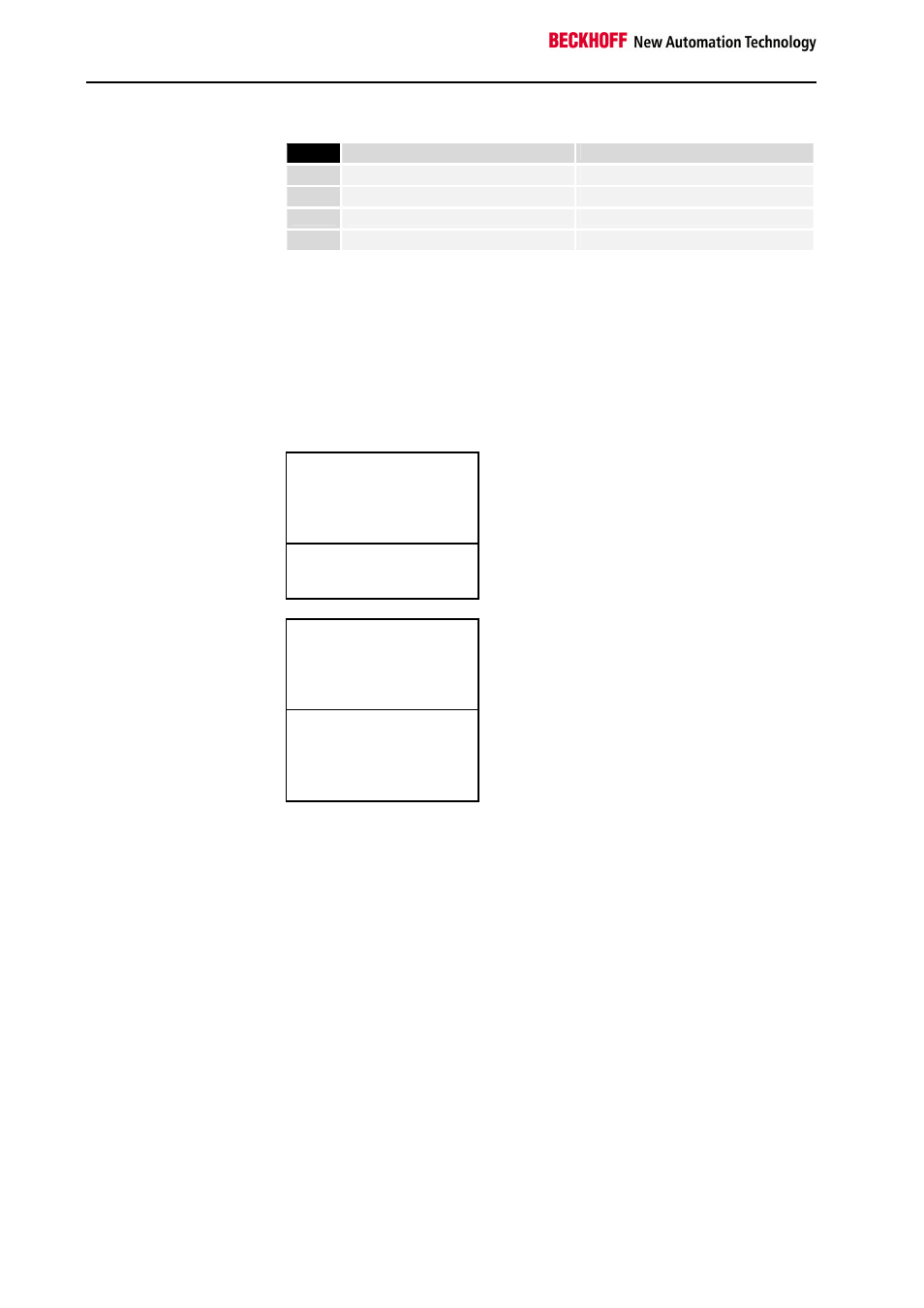
Overview of the breakdown of the process image in the bus coupler:
The „x“ variable represents the number of analog channels. By default, one
channel has one word with 16 bits. The „y“ variable represents the number
of words with digital data. It is calculated on the basis of:
y = ( integral result (number of digital channels / 16) + 1 )
Output data in the
bus coupler
A0
...
byte-oriented data
...
Ax
Ax+1
bit-oriented data
Ax+y
Input data in the
bus coupler
E0
...
byte-oriented data
...
Ex
Ex+1
...
bit-oriented data
...
Ex+y
The path from the I/Os to
the process image in the
InterBus
The bus coupler automatically assigns the I/Os of the terminals to the pro-
cess image in the Interbus protocol. The figure symbolically shows an allo-
cation list. In special applications, the allocation list can be modified to suit
requirements by using the KS2000 configuration software.
The allocation list in the master has the same effect. Byte-by-byte allocati-
on is possible with the Phoenix Contact Firmware version 4.0 and higher.
The master software CMD version 4.0 and higher is needed for this purpo-
se. Setting via FB in the PLC is possible, but is not advisable owing to its
great complexity.