Installation instructions, Appropriate use, Frame sizes and descriptions – BECKHOFF C9900-M298 User Manual
Page 6: Scope of supply, Mounting, Mounting of the wall mounting frame
Installation instructions
Installation instructions
Appropriate use
The C9900 wall mounting frame is designed for Beckhoff Control Panels.
For possible frame and panel combinations please refer to section
The stainless steel mounting frame can be flush-mounted in a solid wall or
screw-mounted in a dry wall.
Frame sizes and descriptions
Frame descriptions
The following frames are available for the different panel sizes:
• C9900-M298 - panel mounting frame for CP6608
• C9900-M311 - panel mounting frame for CP6609/CP6909
• C9900-M313 - panel mounting frame for CP6601/CP6901
• C9900-M314 - panel mounting frame for CP6602/CP6902
• C9900-M316 - panel mounting frame for CP6603/CP6903
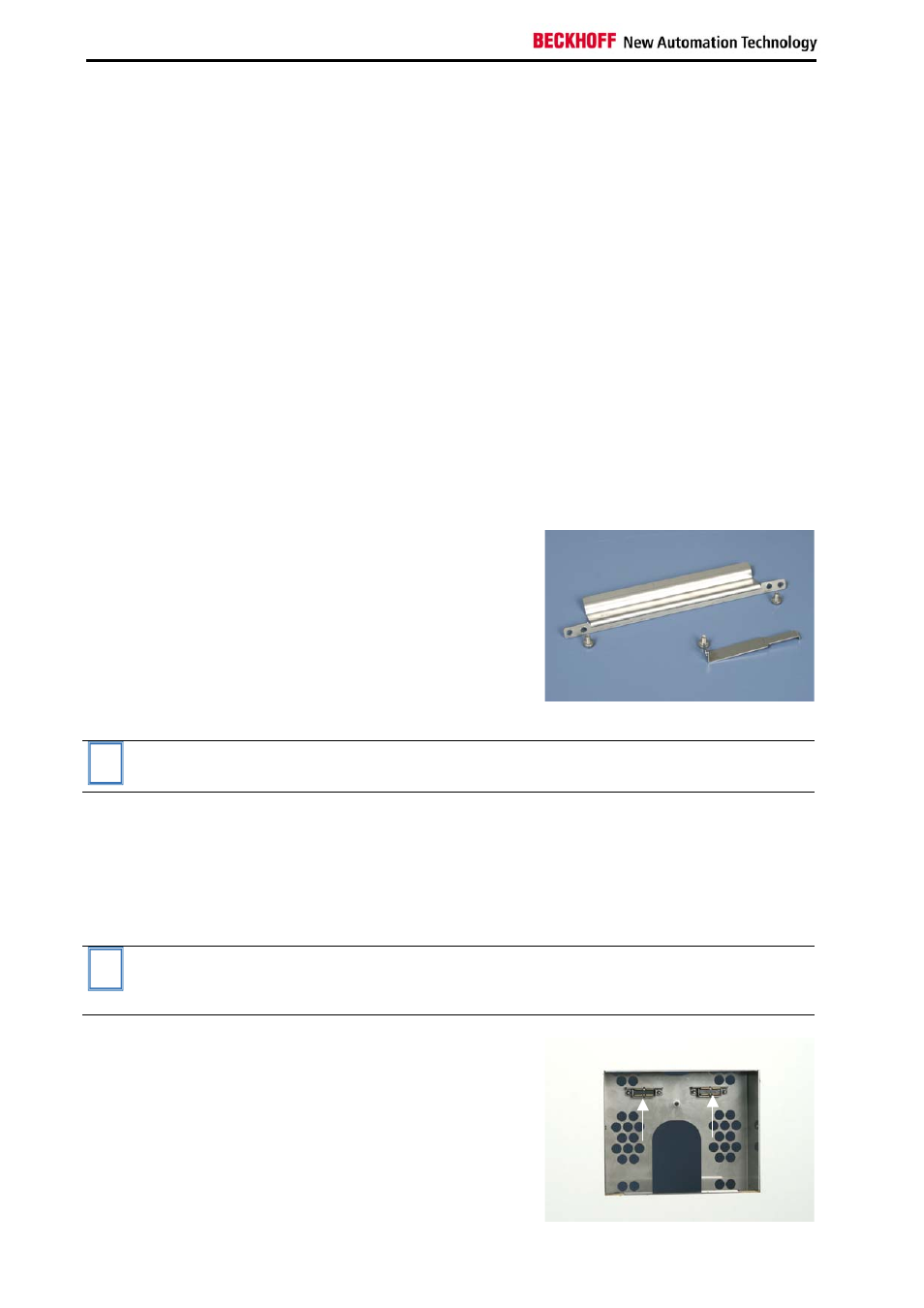
Scope of supply
Scope of supply
The following components are
included:
• 1 panel mounting frame (not
shown),
• 1 mounting bracket (1) and
• 1 fastening bracket (2) for
attaching to the Control Panel,
• 4 bolts M4x5 (3) for fastening
the two brackets.
1
3
3
2
3
i
Note
Only 3 bolts are required for mounting the CP6608 Control Panel (see top
diagram).
Mounting
Mounting of the wall mounting frame
Once the required opening has been prepared (see section
), the mounting frame can be installed in the wall. The frame
design allows for air circulation as required.
i
Note
Ensure that the wall mounting frame is oriented correctly. The pre-
assembled fastening magnets must be positioned at the top of the frame
(see image below).
Wall mounting frame in a
dry wall
The diagram illustrates the
installation of the wall mounting
frame in a dry wall.
The two pre-assembled fastening
magnets are clearly visible at the
top.
4
C9900 wall mounting frame