E figure 5-1, O figure 5-1, N figure 5-1 – Basler Electric BE1-59NC User Manual
Page 34: Figure 5-1
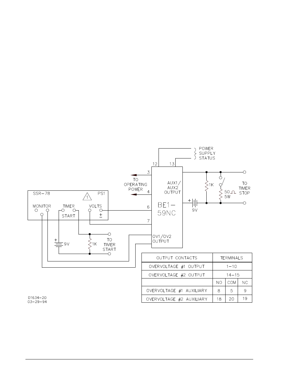
Step 10. Set OVERVOLTAGE 2 TIME DIAL to 001 and apply to case terminals 6 and 7, a voltage that is
10% greater than the value applied in Step 1.
Step 11. Monitor the output terminals indicated in Figure 5-1 for OVERVOLTAGE 2. Remove, and then
reapply the overvoltage at case terminals 6 and 7. Observe the time registered by the counter.
Time must equal the setting
±100 milliseconds or 2%, whichever is greater.
Step 12. Set OVERVOLTAGE 2 TIME DIAL to 010. Monitor the output terminals indicated in Figure 5-1
for OVERVOLTAGE 2. Remove, and then reapply the overvoltage at case terminals 6 and 7.
Observe the time registered by the counter. Time must equal the setting
±100 milliseconds or
2%, whichever is greater.
Step 13. Set OVERVOLTAGE 2 TIME DIAL to 100. Monitor the output terminals indicated in Figure 5-1
for OVERVOLTAGE 2. Remove, and then reapply the overvoltage at case terminals 6 and 7.
Observe the time registered by the counter. Time must equal the setting
±100 milliseconds or
2%, whichever is greater.
Step 14. Set OVERVOLTAGE 2 TIME DIAL to 999. Monitor the output terminals indicated in Figure 5-1
for OVERVOLTAGE 2. Remove, and then reapply the overvoltage at case terminals 6 and 7.
Observe the time registered by the counter. Time must equal the setting
±100 milliseconds or
2%, whichever is greater.
Figure 5-1. Typical Test Setup Timing Option E2
5-2
BE1-59NC Testing
9279400990 Rev D