Equipment required, Single-phase/a-phase trip and dropout test, Equipment required -2 – Basler Electric BE1-87G User Manual
Page 58: Single-phase/a-phase trip and dropout test -2
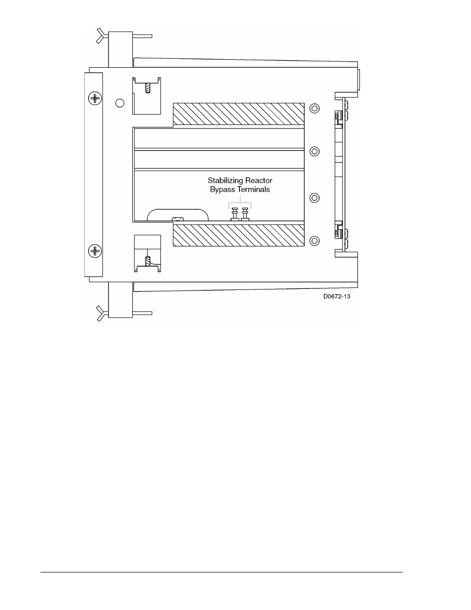
Figure 5-1. Location of Stabilizing Reactor Bypass Terminals (Single-Phase Relays)
Equipment Required
Because of the speed and sensitivity of the BE1-87G, test equipment with appropriate accuracy and
stability must be used to test the sensitivity switch settings. For example, at the most sensitive switch
setting (0.1 ampere), the relay monitors a current difference that is only 1% for a sensing input of 10
amperes.
•
Two adjustable current sources (Doble, AVO, or equivalent equipment)
•
Digital voltmeter (±1% accuracy or better)
•
Digital ammeter (±1% accuracy or better)
•
Variable, 0 to 250 Vac/Vdc power supply (for relay operating power)
•
DC power supply (for current operated targets)
Single-Phase/A-Phase Trip and Dropout Test
Perform the following steps to test the trip and dropout accuracy of relays with single-phase sensing (style
number Sxx-xxx-xxxxx) or phase A of relays with three-phase sensing (style number Gxx-xxx-xxxxx).
1. Connect the test setup shown in Figure 5-2. Current sensing connections should be made at
terminals 6, 7, 8, and 9.
2. Set the sensitivity switch at position A.
3. Apply the appropriate voltage to relay operating power terminals 3 and 4. (A power supply
model/input voltage cross-reference is provided in Table 1-1.)
4. Using a regulated, independently adjustable current source, apply the restraint current to relay
terminals 6 and 9. A current value of 0.1 Aac is applied for relays with style number x1x-xxx-xxxxx
and a current value of 0.02 Aac is applied for relays with style number x2x-xxx-xxxxx.
5-2
BE1-87G Testing and Setting
9170800990 Rev N