Basler Electric BE1-50/51B-240 User Manual
Page 26
18
9252000790 Rev B
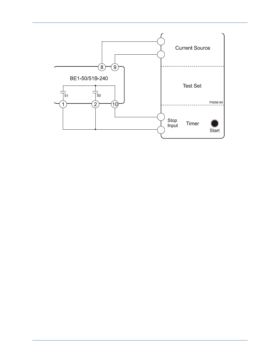
Figure 10. 51 Pickup, Time Dial, Integrating Reset, 50 Pickup, and Manual Trip Test Setup
Time Dial
1.
Connect and configure the relay for time dial testing:
a.
Connect the test setup shown in Figure 10.
b.
Set circuit board switch SW3 as follows:
SW3-1 = ON for 50 Hz operation or OFF for 60 Hz operation
SW3-2 = OFF (no additional time delay for the 50 element)
SW3-3 = ON (Westinghouse CO type characteristic curves)
SW3-4 = ON (integrating reset characteristic)
c.
Set TIME DIAL to 4.5.
d.
Set CURVE to S.
e.
Set TIME PICKUP to 1.0.
f.
Set INST PICKUP to 90.
2.
Prepare to apply 1.5 Aac to terminals 8 and 9 and record the elapsed time from when current is
applied until the 51 output contacts close.
3.
Apply the current (step from 0 to 1.5 Aac) and record the elapsed time. The elapsed time should be
between 0.345 and 0.424 seconds. (This tolerance is greater than
±2% because it is the
accumulation of both pickup and timing tolerances.)
4.
Remove the input current.
Integrating Reset
1.
Connect and configure the relay for integrating reset testing.
a.
Connect the test setup shown in Figure 10.
b.
Set circuit board switch SW3 as follows:
SW3-1 = ON for 50 Hz operation or OFF for 60 Hz operation
SW3-2 = OFF (no additional time delay for the 50 element)
SW3-3 = ON (Westinghouse CO type characteristic curves)
SW3-4 = ON (integrating reset characteristic)
Testing
BE1-50/51B-240