Balanced Audio VK-P12SE Phonostage User Manual
Page 10
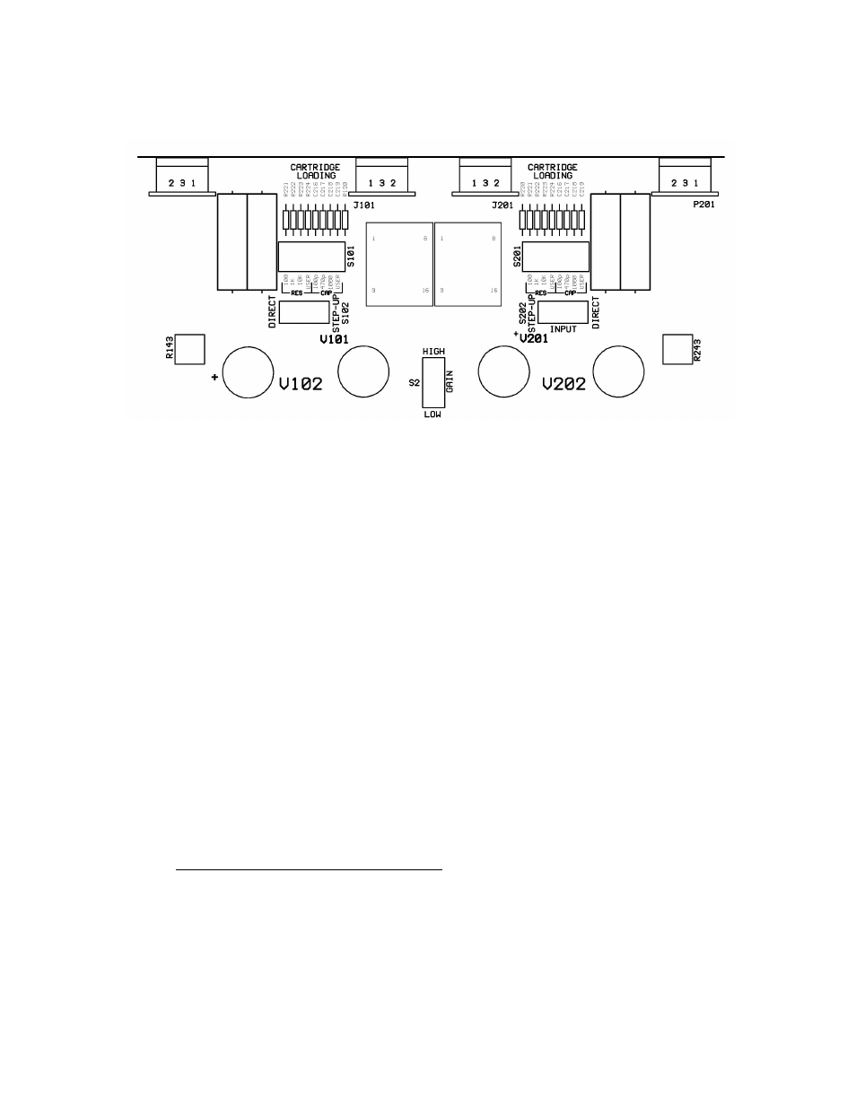
The following section describes the operation of these controls.
Figure 1
Cartridge loading switches S101 and S201
Resistance:
The 47K load resistor is permanently connected to the cartridge input. If
a different loading value is desired, it can be obtained by switching in
additional resistors, installed on the
VK-P12SE PC board. This is accomplished by using the two DIP switches,
S101 and S201, that allow multiple choices for resistive and capacitive
cartridge loading. Four positions are reserved for the choice of resistance
and four for capacitance. Out of each group of four, one position is loaded
with female pins and allows the user to install any desired value component
(this position is marked “USER”). Gold-plated solderable pins are supplied
with the VK-P12SE accessory kit, that should be attached to either resistors
or capacitors supplied by the user. This allows for easy installation and
upgrade of user-supplied components.
The following resistors can be added in parallel with the 47K load:
Switch position
Resistor Value
1
100 Ohm
2
1K
3
10K
4
User-Defined
Any parallel combination of the these values is also allowable.