ART Pro Audio MX624 - Six Channel Stereo Mixer User Manual
Page 4
4
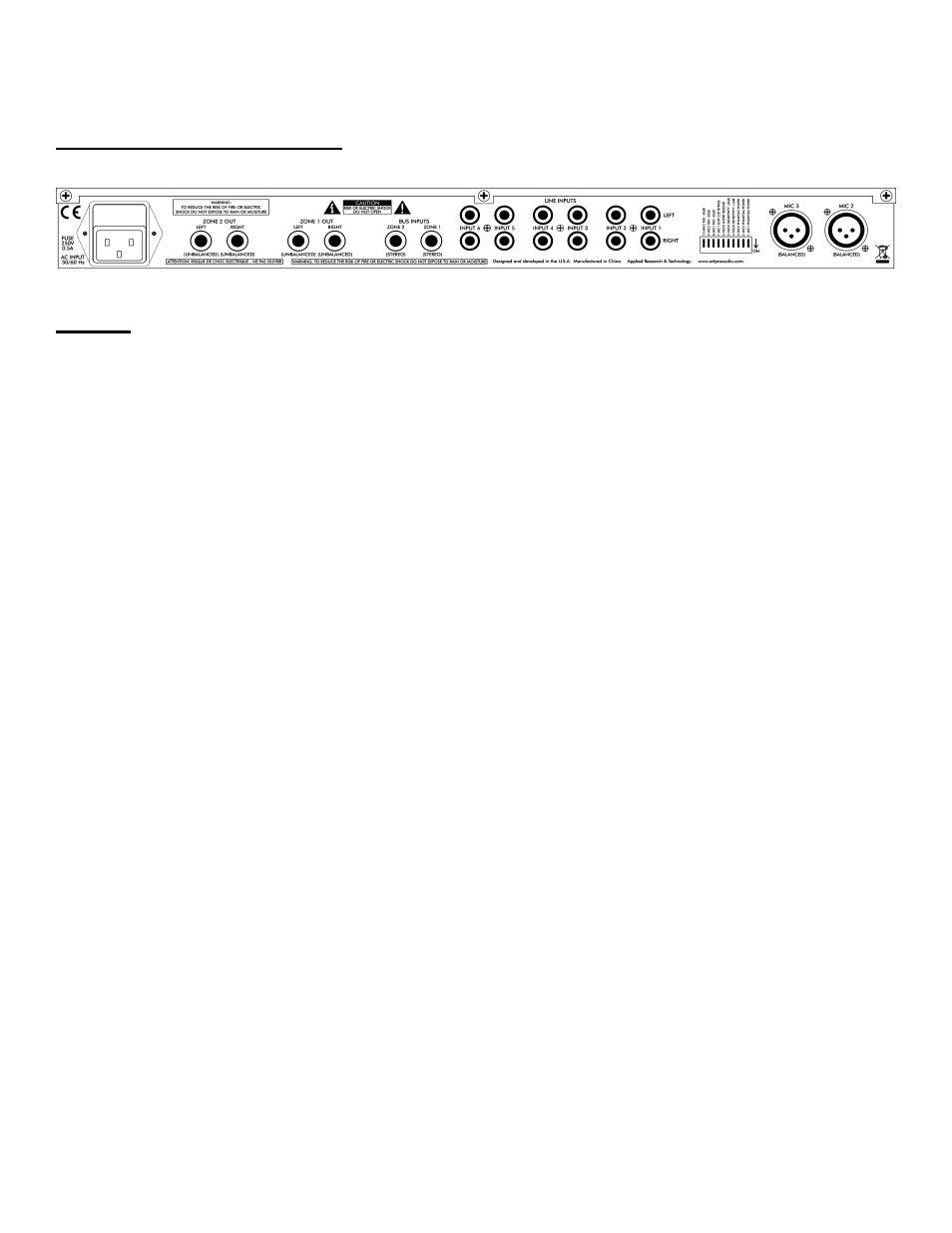
CONNECTIONS
Rear Panel Connections
Inputs
MIC 2 and MIC 3
Each of these two female XLR connectors provides a balanced mono input for a
microphone, which typically outputs lower signal levels. An additional 26 dB of gain is
provided to boost the mic signal to near line level. The mono signal of each mic input is
fed to both left and right stereo channels and mixed with the line-level input signals
from the RCA jacks of the same channel. This combined signal may be assigned to
either Zone 1 or Zone2.
+48V phantom power is available to operate those microphones that contain active
electronic circuitry (such as condenser mics) and may be applied by setting the
corresponding PHANTOM POWER switch in the down (ON) position. The switches are
located towards the right of the rear panel. See page 8 (Rear Panel Controls) for
more information. Note: Do not apply phantom power unless the microphone is
designed to use it.
LINE INPUT 1 through 6 (LEFT and RIGHT)
Each of these six stereo pairs of RCA phono jacks provide unbalanced inputs for line
level signals. The top row of jacks is for left channel connections and the bottom row is
for right channel connections.
ZONE 1 and 2 BUS INPUTS
These stereo (TRS) phone jacks provide a direct buffered input connection to the
MX624's internal zone buses. They can be used to chain multiple MX624's together,
using special cables with dual 1/4-inch mono (TS) phone plugs connected to a single
1/4-inch stereo (TRS) phone plug (tip is left and ring is right). Be sure the connections
use shielded cable. Then simply connect the ZONE 1 or 2 OUT (or both) jacks of one
MX624 to the ZONE 1 or 2 BUS INPUT (or both) jacks of another MX624.