Argox R Series User Manual
Page 69
69
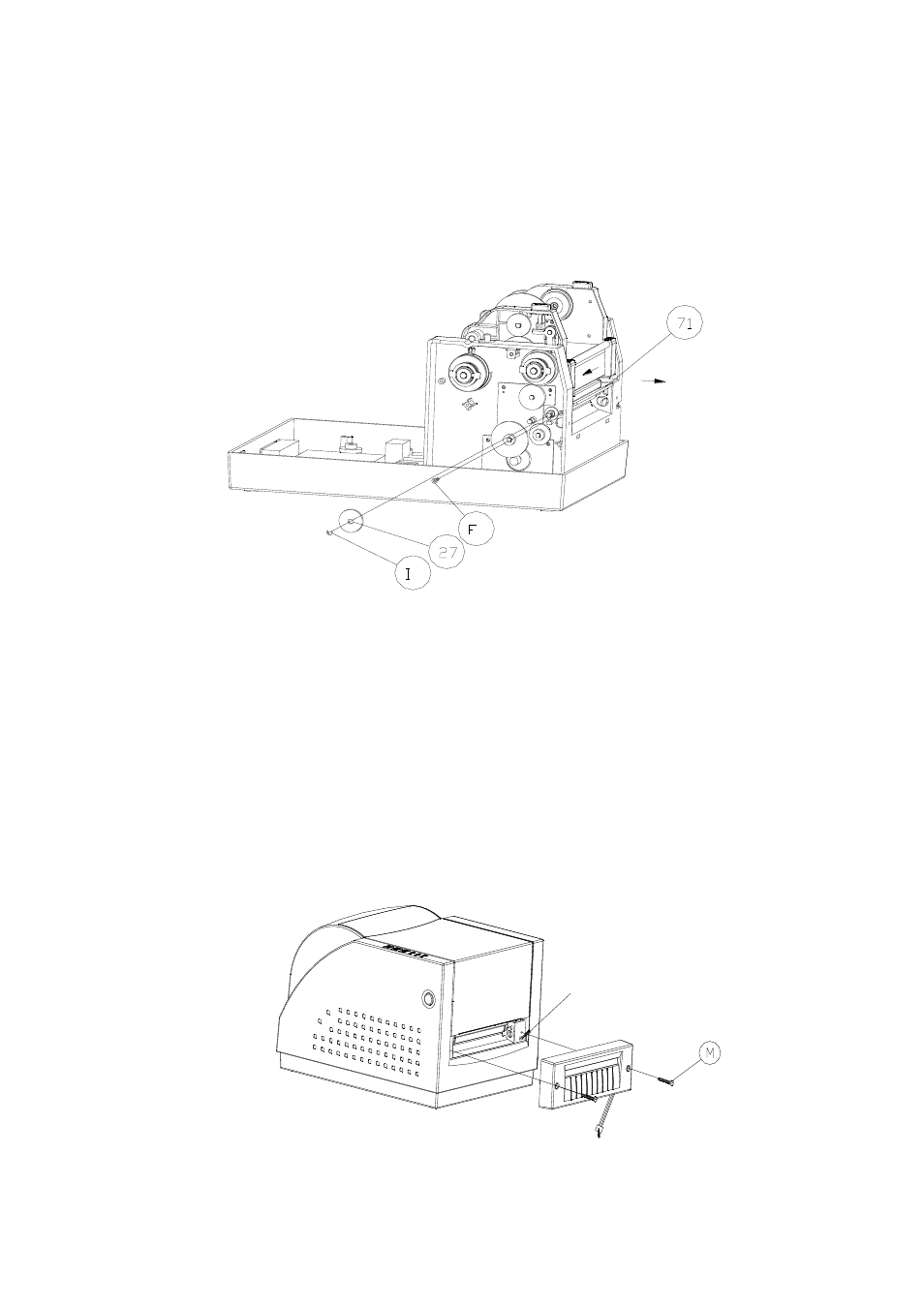
1. Remove the E- ring(I), gear(27) and release the
screw(F).
2. Remove the bracket-peeler(71) from the module.
3. Secure two attached screws (B) for the cable
connector.
4. Add a baby board to JP29 on the main board.
5. Plug the cable connector into JP13, and make sure
Ju
mper (J1) position is “2-3”
6. Click back the middle cover.
7. Click back the top cover.
8. Secure two attached screws (M) for the cutter.
9.
Plug cutter cable into “ External Connector”.
External Connector
Cutter Cable