Reflex power™ fault protection groups – AMETEK ReFlex Fault Protection Groups User Manual
Page 3
Technical Note
ReFlex Power™ Fault Protection Groups
Document No. M380595-TN Rev A • 01/08/09
©2009 AMETEK Programmable Power, Inc. • All rights reserved. • AMETEK is a trademark of AMETEK, Inc.
9250 Brown Deer Road, San Diego CA 92121 • Tel: 858-450-0085 • Fax: 858-458-0267 • email:
• Web:
www.programmablepower.com
3 of 4
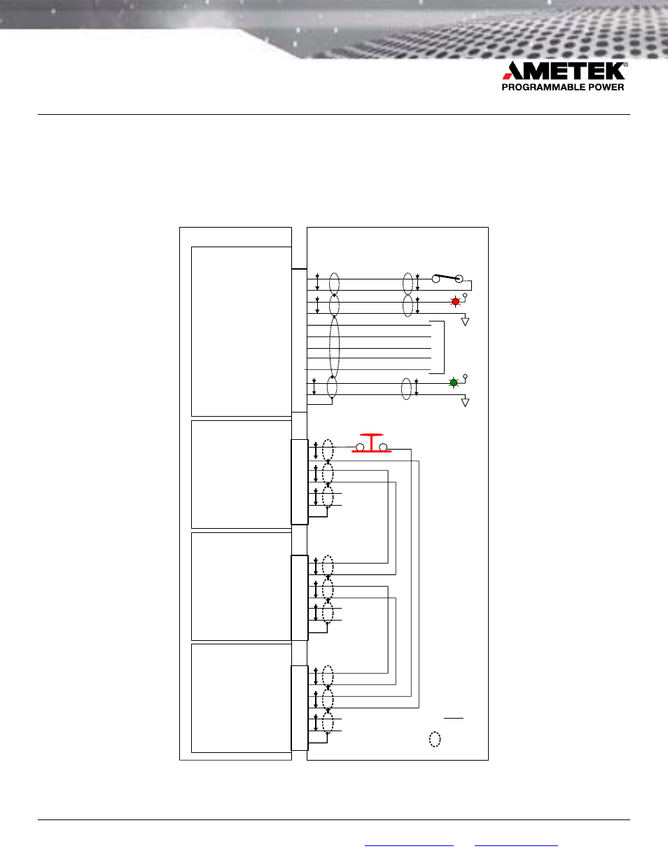
The following diagram depicts all the required connections to
implement an entire system fault group. An external Panic
Switch is included in the diagram to define the
interconnections for an operator commanded shutdown. In
this application, the Panic Switch shall allow all interconnected
modules to follow the function of the switch. Since no fault has
been reported, the user may use this feature to command all
power modules off.
An external Interlock Switch is shown connected to the
Remote Inhibit pins of the Controller module to prevent turning
on power module outputs until conditions are safe. Finally, the
Discrete Fault Indicator (DFI) and Power On (PWR ON) output
signals of the Controller are shown illuminating indicators in
the user space.
12
Power Module 1
Interface Connector
Controller Interface
Connector
RI
CHAS-GND
DFI-RTN
DFI
RI-RTN
1
2
8
9
T/P
10
T/P
T/P
Power Module 2
Interface Connector
Power Module
n
Interface Connector
Panic
Switch
ENA
ENA-RTN
1
6
MODF/TRIG-OUT-RTN
MODF/TRIG-OUT
7
2
TRIG-IN
TRIG-IN-RTN
CHAS-GND
3
8
5
T/P
T/P
T/P
DIG-I/O-RTN
DIG3-I/O
DIG2-I/O
DIG1-I/O
DIG0-I/O
4
5
13
6
3
11
PWR ON-RTN
PWR ON
T/P
T/P
ENA
ENA-RTN
1
6
MODF/TRIG-OUT-RTN
MODF/TRIG-OUT
7
2
TRIG-IN
TRIG-IN-RTN
CHAS-GND
3
8
5
T/P
T/P
T/P
ENA
ENA-RTN
1
6
MODF/TRIG-OUT-RTN
MODF/TRIG-OUT
7
2
TRIG-IN
TRIG-IN-RTN
CHAS-GND
3
8
5
T/P
T/P
T/P
T/P
User Space / Interface Test Adapter
Interlock
Switch
Fault
Power
Digital
I/O
Lines
Trigger
Input
Trigger
Input
Trigger
Input
+V
+V
NOTE:
T/P = Twisted Pair
= Shield
Detailed Fault Protection Group Wiring Diagram