Reflex power™ fault protection groups, Theory of operation, User application wiring – AMETEK ReFlex Fault Protection Groups User Manual
Page 2
Technical Note
ReFlex Power™ Fault Protection Groups
Document No. M380595-TN Rev A • 01/08/09
©2009 AMETEK Programmable Power, Inc. • All rights reserved. • AMETEK is a trademark of AMETEK, Inc.
9250 Brown Deer Road, San Diego CA 92121 • Tel: 858-450-0085 • Fax: 858-458-0267 • email:
• Web:
www.programmablepower.com
2 of 4
THEORY OF OPERATION
Fault Protection Groups may be implemented by external user
wiring through the ReFlex Power
TM
front panel Interface
connector on each DC power module. The flexible user im-
plementation allows the creation of three basic fault group types:
• Single Fault Protection Group: All ReFlex Power
TM
DC
modules externally interconnected to provide immediate
shut down all DC power module outputs upon a fault
condition in any DC power module.
• Multiple Independent Fault Protection Groups: Groups
of ReFlex Power
TM
DC modules independently
interconnected to shut down of all DC power module
outputs within each independent group without affecting the
functions of other independent groups.
• Multiple Dependent Fault Protection Groups: Using an
external resistor and Schottky Diode the user may create
dependent Fault Protection Groups wherein a fault in Group
A will shut down all DC power modules in Group A and
Group B, but a fault in Group B will not affect the module
outputs in Group A. The following diagram depicts the
external wiring required to create each of these Fault
Protection Group types.
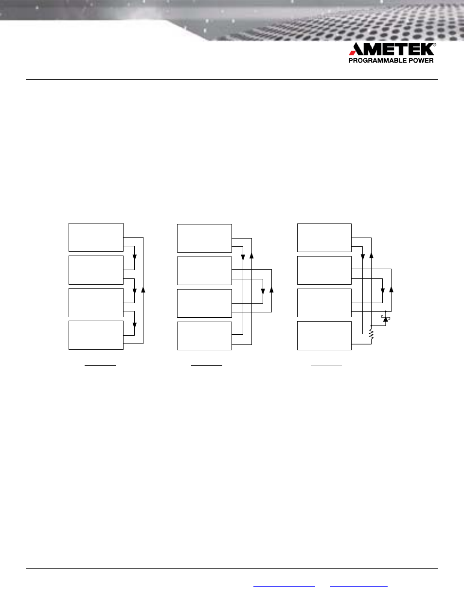
USER APPLICATION WIRING
ENA
MODF-OUT
Module 1
ENA
MODF-OUT
Module 4
ENA
MODF-OUT
Module 3
ENA
MODF-OUT
Module 2
ENA
MODF-OUT
Module 1
ENA
MODF-OUT
Module 4
ENA
MODF-OUT
Module 3
ENA
MODF-OUT
Module 2
Example 1
Example 2
Single (System)
Fault Group
Multiple, Independent
Fault Groups
ENA
MODF-OUT
Module 1
ENA
MODF-OUT
Module 4
ENA
MODF-OUT
Module 3
ENA
MODF-OUT
Module 2
Example 3
Multiple, Dependent
Fault Groups
R
TBD
1
2
1
2
1
2
1
2
1
2
1
2
1
2
1
2
1
2
1
2
1
2
1
2
Example 1 depicts the MODF-OUT signal of Module 1
connected to the ENAble input of Module 2. This method is
repeated from module-to-module until the final module MODF-
OUT signal is connected back to the ENAble input of Module
1. A fault condition on any module will assert the MODF-OUT
signal to the next power module ENAble line, causing it to de-
assert its enable (disable) and shutdown the module output.
This chain reaction quickly disables the outputs of all DC
power modules within the system. Since the ENAble inputs
are de-asserted on all other modules in the chain, only the
module with the fault that started the sequence will indicate a
fault condition. All connected modules shall remain latched in
shutdown until the original fault condition is cleared.
Example 2 depicts two independent fault groups connected in
a similar fashion. Module 1 and Module 4 will shutdown when
either experiences a fault condition. Likewise, Module 2 and
Module 3 will shutdown when either experiences a fault
condition. However, the fault group comprised of Module 1
and Module 4 will continue to operate independently of a fault
condition with Module 2 and Module 3.
In Example 3, if either Module 2 or 3 faults off, then Modules 1
and 4 will also shutdown; however, if either Module 1 or 4
faults off, then Modules 2 & 3 will not be shut down