Vectronics VC-300DLP User Manual
Page 5
VC-300DLP Antenna Tuner
Owner's Manual
5
5. Connect any antenna that does not require the use of a tuner to the BYPASS (4) connector
using a coax cable. this allows you to select this antenna from the OUTPUT SELECTOR
switch.
6. To avoid possible damage to the VC-300DLP, set the TRANSMITTER, ANTENNA, and
RANGE switches as outlined in the next section before applying transmitter power.
7. Begin tuning with your transmitter set at a low output power setting (10 to 20 W).
WARNING: DO NOT OPERATE THE VC300DLP WITH TE COVER OFF! DO NOT
CHANGE THE INDUCTOR SWITCH WITH MORE THTN 20 WATTS
OF APPLIED POWER
TUNING
1. Select the band and frequency of desired operation.
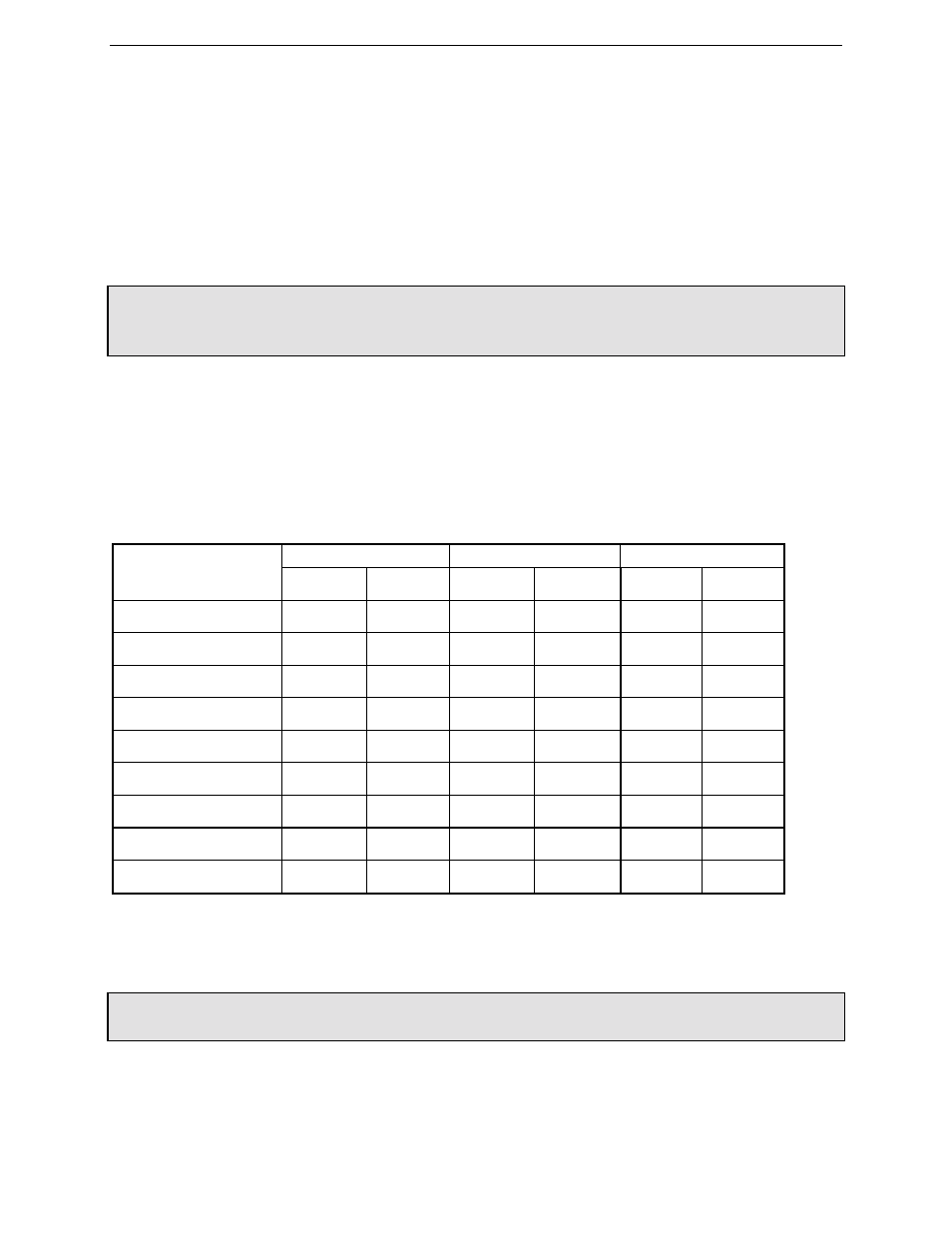
2. Set TRANSMITTER, ANTENNA, and INDUCTOR controls to the suggested settings before
applying transmitter power. Actual settings may vary from antenna to antenna.
Band /
TRANSMITTER
ACTUAL
INDUCTANCE
Frequency
Sug. Actual Sug. Actual Sug. Actual
160 M / 1.8 MHz
5.1
3.0
J+
75 M / 3.75 MHz
5.1
3.0
D-
40 M / 7.15 MHz
6.0
4.1
B
30 M / 10.125MHz
6.0
4.2
B-
20 M / 14.175 MHz
5.5
4.2
A+
17 M / 18.118 MHz
5.0
3.8
A+
15 M / 21.225 MHz
5.2
6.0
A+
12 M / 24.940 MHz
4.8
4.8
A+
10 M / 28.850 MHz
4.0
6.0
A+
3. Set your transmitter to a low power output. If your transmitter has a TUNE position, select
that position.
WARNING: DO NOT EXCEED 150 WATTS ON ANY BAND WHERE THE SWR ON
THEANTENNA IS GREATER THATN 4 TO 1.
4. Set RANGE switch to 30 Watts (button IN).