Vectronics VEC-1402DK User Manual
Page 10
VEC-1402DK Instruction Manual
High Performance 2 Meter Pre-Amp Kit
8
STEP-BY-STEP ASSEMBLY INSTRUCTIONS
Before assembling your kit, please take time to read and understand the VEC kit
warranty printed on the inside cover of this manual. Read through the assembly
instructions to make sure the kit does not exceed your skill level. Once you
begin construction, the kit is non returnable. Finally, if you haven't already
done so, please verify that all parts listed in the inventory are included. If
anything is missing or broken, refer to the warranty instructions for replacing
missing or damaged parts.
Part designators for components such as R1, C3, etc., appear on the silk-
screened legend on the component-mounting side of the printed circuit board.
These correspond to the parts placement drawing shown earlier in this manual.
The parts are inserted on the silk-screened side of the board.
Except for Q1, none of the parts used in this preamp are “polarized,” so it makes
no difference which way the parts are inserted into the board. If you insert the
capacitors so the values face the board edges, it will be easier to read the values
when checking for misplaced components during troubleshooting.
If you have any last-minute questions concerning tools or materials needed to
assemble this kit, please refer to the section entitled "Before You Begin." The
directions use two sets of check boxes. Check one when a step is complete and
use the other for double-checking your work before operation. Start kit
assembly by mounting Q1 and the components located on the left end of the PC
board.
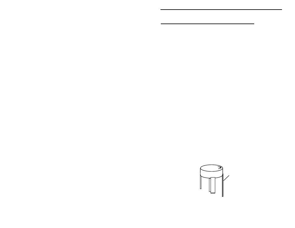
! ! 1. Locate transistor Q1, a MRF 901. This device resembles a small black
plastic pill. Note that the longest lead is the collector. The collector is
distinguished by the letter “M” marking on the device body. Carefully
bend each transistor lead down, forming a right-angle to the
component body (the "M" should be on top):
Collector
MRF901
! ! 2. Locate the silk-screened footprint for Q1, almost dead-center on the
PC board. Note that the long collector lead is oriented toward