1 charge cooler installation, Charge cooler installation -1, Charge cooler installation – Paxton Superchargers GM 8.1 HD Truck/SUV User Manual
Page 35
13-1
P/N: 4809642
©2004 Paxton Automotive
All Rights Reserved, Intl. Copr. Secured
28SEP04(4809642 v1.2)8.1GMTruck
Section 13
CHARGE COOLER INSTALLATION
A.
Install the 1/2" NPT x 3/4" 90° and straight
brass fittings into the charge air cooler using
thread sealant on the threads. (See Fig.
13-a.)
Fig. 13-a
Fig. 13-b
13.1
CHARGE COOLER INSTALLATION
B.
Install the Ø2.75" x 3" sleeve on the dis-
charge of the supercharger. Using the 2.75"
sleeve and #44 hose clamps, connect the
inlet of the Charge Air Cooler to the dis-
charge of the supercharger.
C.
Install the Ø2.75" end of the 3.0"-2.75"
reducer on the outlet side of the Charge Air
Cooler.
D.
Trim the Ø3.88" end of the 90° silicone
elbow (see Fig. 13-b) to allow for hood
clearance when the discharge duct is
installed.
E.
Install the trimmed end of the 90° silicone
elbow onto the throttle body. Orient the sili-
cone elbow so that it is pointing toward the
passenger side. Slide the long side of the L-
shaped discharge tube into the Ø3.0" end of
the silicone reducer. Install the remaining
end into the 90° silicone elbow attached to
the throttle body. Secure the Charge Air
Cooler assembly and discharge tube using
the #44, #48 and #64 hose clamps.
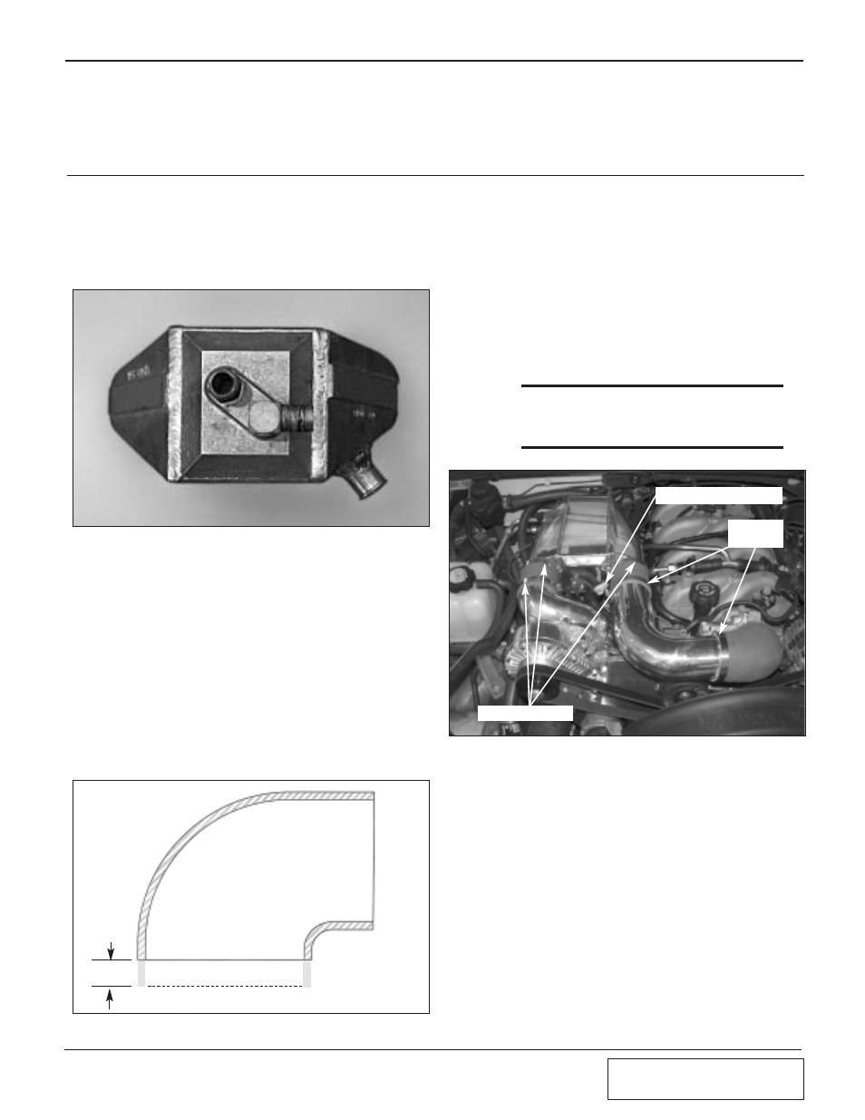
***NOTE:***
It may be necessary to slightly modify the
location of the dipstick so that it locates to the
position shown. (See Fig. 13-c.)
TRIM
.750
Fig. 13-c
NEW DIPSTICK LOCATION
#48 HOSE
CLAMPS
#44 HOSE CLAMPS