Nise 105 system components, Chapter 2: jumpers and connectors – NEXCOM NISE 105 User Manual
Page 22
Copyright © 2013 NEXCOM International Co., Ltd. All Rights Reserved.
9
NISE 105/105A User Manual
Chapter 2: Jumpers and Connectors
NISE 105 System Components
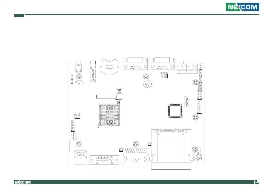
The NISE 105 system is made up of a NISB 105 motherboard and an I/O daughterboard. This chapter lists the location and pinout assignment of the jumpers
and connectors on each component.
BAT1
H5
H1
SW2
R339
S1
P17
3
1
4
2
JP11
3
1
2
JP10
B9
B10
B2
B1
A9
A10
A2
A1
LAN1
D13
16
24
9
1
17
CN10
5
13
4
1
10
9
CN9
4
1
4
1
JP16
4
1
4
1
4
1
10
2
9
1
7
1
8
2
6
1
7
2
3
1
8
4
6
5
CN4
7
2
3
1
8
4
6
5
CN3
1
10
U20
128
97
96
65
64
33
32
1
1
3
1
3
6
1
9
5
6
1
5
9
CN2
BZ1
BJ
BH
BG
BA
BC
BE
AR
AU
AW
AL
AN
AC
AE AG AJ
W
AA
R
U
N
G
J
L
A
C
E
53
51
49
47
45
43
41
39
37
35
33
31
29
27
25
23
21
19
17
15
13
11
9
7
5
3
1
U22
CN6
5
1
6
2
JFW1
4
1
1
2
3
1
3
1
14
13
2
1
JP9
USB2.0
HDMI
BATTERY
COM4
COM3
MIC IN
LINE OUT
USB2.0
USB3.0
DVI-I
LAN1
LAN2
CFAST
SW1
CN7
CN9
CN10
LAN1
CN8
JP9
JP11
JP10
JP12
J2
JP8
JP13
JP6
CN4
CN3
JP4
JP3
JP16
CN2
CN1
CN6
CN5
BAT1
JP2
JP1
SW2
JFW1
JP7
JP5
Locations of the Jumpers and Connectors for NISB 105