Ivie iFlex 2400 Series User Manual
Page 4
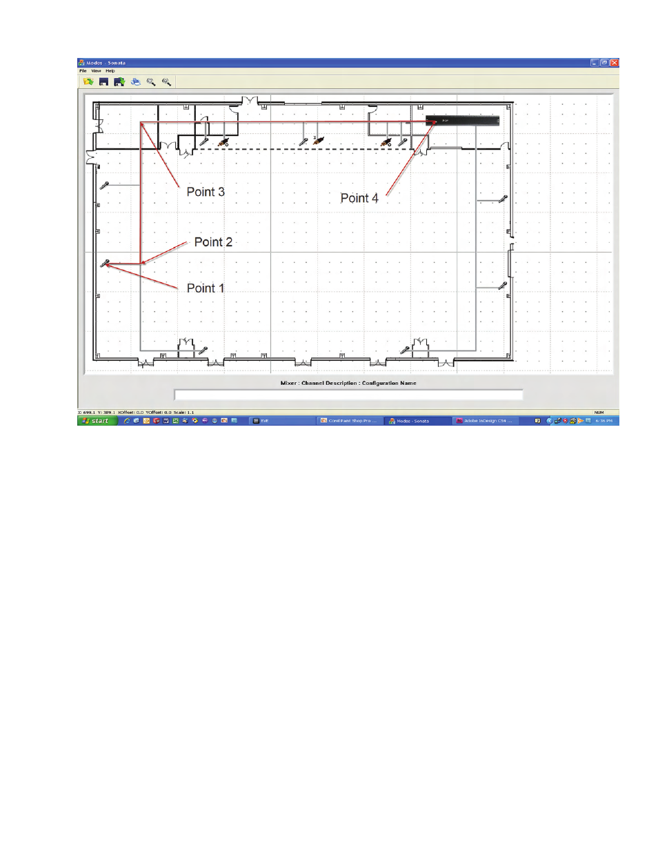
Figure 2
Input Placement
Placing inputs is a simple matter of right-clicking
anywhere in the layout area and choosing the
‘Create Input’ option. This will place a small
graphic of a microphone onto the layout wherever
the mouse pointer is located. The icon can
be scaled, moved and deleted using normal
Windows
TM
conventions.
If a line input or output is desired, right-click and
select the ‘Create Line Input’, or ‘Create Line
Output’ options. In this case a small connector
icon with the letter ‘I’ or ‘O’ will be created.
The iFlex
TM
mixer is placed in the same manner
as the inputs above. Right-click anywhere in the
layout, and select the ‘Create Mixer’ option. Like
inputs, the mixer may be re-sized and/or moved to
fit appropriately on the background.
Connections
Each input, or line output, must be connected to a
mixer. In multi-box systems this is used to deter-
mine which inputs or line outputs are connected
to which mixers. In a single mixer design, all are
connected to the same mixer.
To connect inputs and line outputs to a mixer,
simply right-click on the input or line output icon,
and select ‘Connect’. Connection lines are created
as polylines, with the first point at the input or line
output icon, any number of intermediate points,
and a final point at the mixer icon (make sure your
last point is inside the mixer icon area).
For simplicity in layout, it is often more visually
appealing to overlay lines on top of one another
(as in figure 2 above). Make sure all inputs and
line outputs are connected to a mixer.