Ivie iFlex 2400 Series User Manual
Page 10
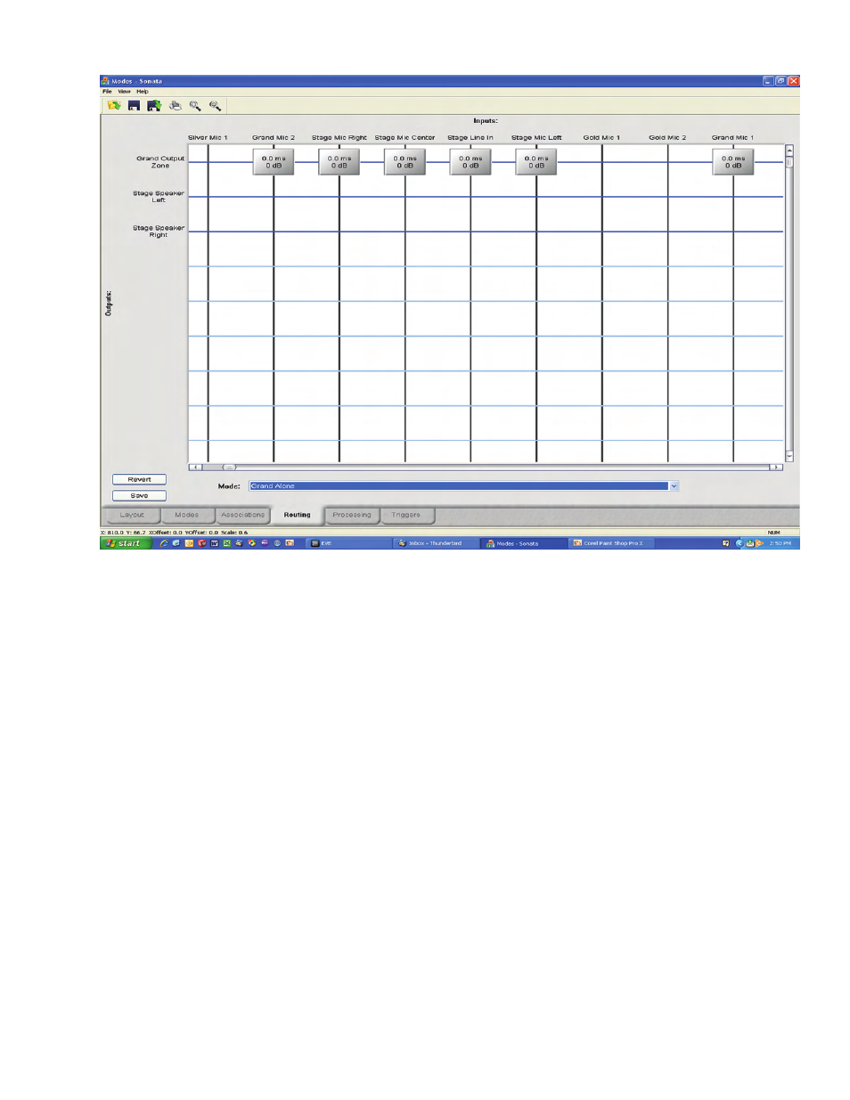
Figure 7
arrows will appear to the left of every input or
output that contains an association for that mode.
This allows the user to change the priority of that
mode as it relates to other modes for that input or
output. Higher priorities are to the left, and lower
to the right. For this example, make sure to follow
the priorities as shown on figure 6.
Routing
By clicking the routing tab in the lower-left corner
of the screen, the user is taken to the routing
screen. This screen allows the user to define the
mix for each existing mode.
By selecting the mode in the section box in the
lower-center of the screen, the outputs of that
mode are displayed on the left side of the matrix.
Only outputs associated with that mode will be
displayed on the left side, but all inputs of the
system will be displayed above the matrix.
To place a mix node, simply click at the
intersection of the input and output. A rectangular
mix node will appear, with information on delay
and gain for that node.
In the example above, The mode “Grand Alone”
has been selected. Notice that the inputs for the
stage and the two microphones have all been
selected to be mixed into the output “Grand Output
Zone”. If the “Grand + Silver” output were
selected, the user would see all the outputs from
the grand, and all the outputs from silver combined
into the outputs for grand and silver.
To modify the delay or gain of a node, right-click
on the node, and edit the available properties. This
provides a full cross-point delay and gain for the
user.
After defining each zone, the results should look
like those in the file “XXX”.