Drawing view27, Drawing view28, Section view a-a – Future Automation LA User Manual
Page 5: Detail view b (1 : 5), Future automation, Stage 3, La - lifting arm instructions
Lid
Mounts
Detail B
Section AA
A
A
TOP
B
Safety Switches
Top Panel
3
Safety Edge
Stage 3
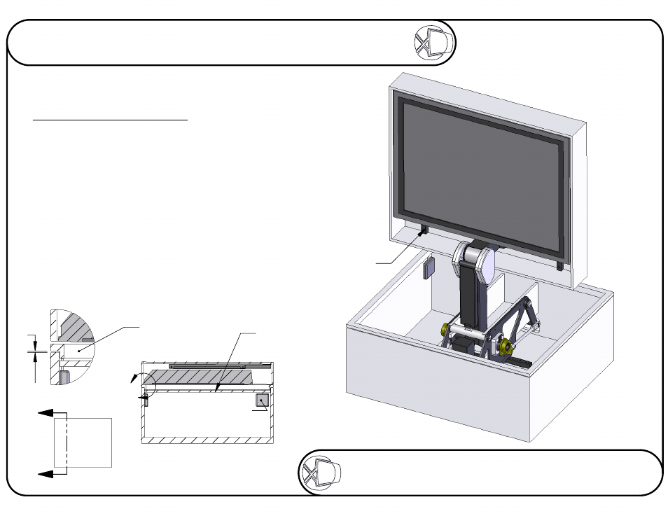
Fitting Lid and Switches
The lid can be fitted using screws and washers
through the 10 holes in the Lid Mounts.
See the technical sheet showing the cabinet
dimensions, to determine the gap above the
screen.
The four safety switches can be screwed to
the side of the box. They line up with the cut
outs in the Top Panel. Set up so that the safety
edge can move down 3 to 5mm and operate
the switches. When plugged into the control
box they will stop the mechanism.
Sheet 5 of 8
ISSUE: 001
www.futureautomation.co.uk
FUTUREAUTOMATION
LA - Lifting Arm
Instructions