1 aud-d2a aes/ebu digital audio connector, 2 aud-d2a analog audio out connector – Doremi DCP-2000 User Manual
Page 6
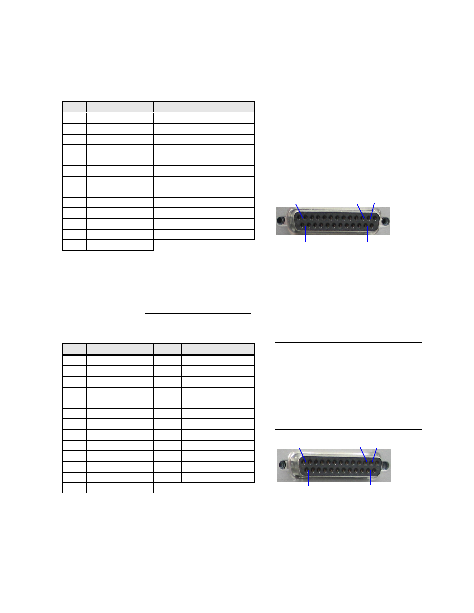
2.2.1 AUD-D2A AES/EBU Digital Audio Connector
The DB25-F digital audio input connector pin-out complies with the AES/EBU standard. Its pin-out
follows:
Pin #
Signal Description
Pin #
Signal Description
1
no connection
14
no connection
2
no connection
15
no connection
3
no connection
16
no connection
4
no connection
17
no connection
5
no connection
18
no connection
6
no connection
19
no connection
7
Ch 7 & 8 plus
20
Ch 7 & 8 minus
8
Ch 7 & 8 ground
21
Ch 5 & 6 plus
9
Ch 5 & 6 minus
22
Ch 5 & 6 ground
10
Ch 3 & 4 plus
23
Ch 3 & 4 minus
11
Ch 3 & 4 ground
24
Ch 1 & 2 plus
12
Ch 1 & 2 minus
25
Ch 1 & 2 ground
13
no connection
The cable that is used to interconnect the DCP-2000 to the AUD-D2A is a one to one pin
compatible.
2.2.2 AUD-D2A Analog Audio Out Connector
The product ships with un-balanced output ONLY. The DB25-F connector for the Analog Audio
Output has the following pin-out:
Un-balanced output:
Pin #
Signal Description
Pin #
Signal Description
1
Ch 8 plus
14
no connection
2
Ch 8 ground
15
Ch 7 plus
3
no connection
16
Ch 7 ground
4
Ch 6 plus
17
no connection
5
Ch 6 ground
18
Ch 5 plus
6
no connection
19
Ch 5 ground
7
Ch 4 plus
20
no connection
8
Ch 4 ground
21
Ch 3 plus
9
no connection
22
Ch 3 ground
10
Ch 2 plus
23
no connection
11
Ch 2 ground
24
Ch 1 plus
12
no connection
25
Ch 1 ground
13
no connection
D2K.OM.000663.DRM
Page 6
Version 1.2
Doremi Cinema LLC
DCI Channel Map:
Channel 1: L
(screen, left)
Channel 2: R
(screen, right)
Channel 3: C
(screen, center)
Channel 4: LFE (screen, low frequency effects
subwoofer)
Channel 5: Ls
(surround, left wall)
Channel 6: Rs
(surround, right wall)
Channel 7: Lc
(screen, mid left to center)
Channel 8: Rc
(screen, mid right to center)
Pin 1
Pin 25
Pin 2
Pin 13
Pin 14
Pin 1
Pin 25
Pin 2
Pin 13
Pin 14