Installing visionswitch, Video inputs/ outputs, Jumper links – Datapath VisionSwitch User Manual
Page 5
5
Installing VisionSwitch
Note:
You are likely to need a flat blade and a Phillips head screwdriver for the installation so
please ensure you have these to hand before you begin.
Power down your complete system (including peripherals) at the PC and the main power supply.
Disconnect all the cables connected to the PC, noting the positions for correct reconnection after
the VisionSwitch is installed. Carefully remove the cover from your PC.
Locate an available PCI slot to install your Vision Switch. You may need to remove the expansion
slot cover and screw, please retain these for future use.
Holding the card firmly by its top edge at each end of the card’s length, slide it into the slot.
Using the retain screw, secure the bracket to the back panel.
Replace the cover on your PC.
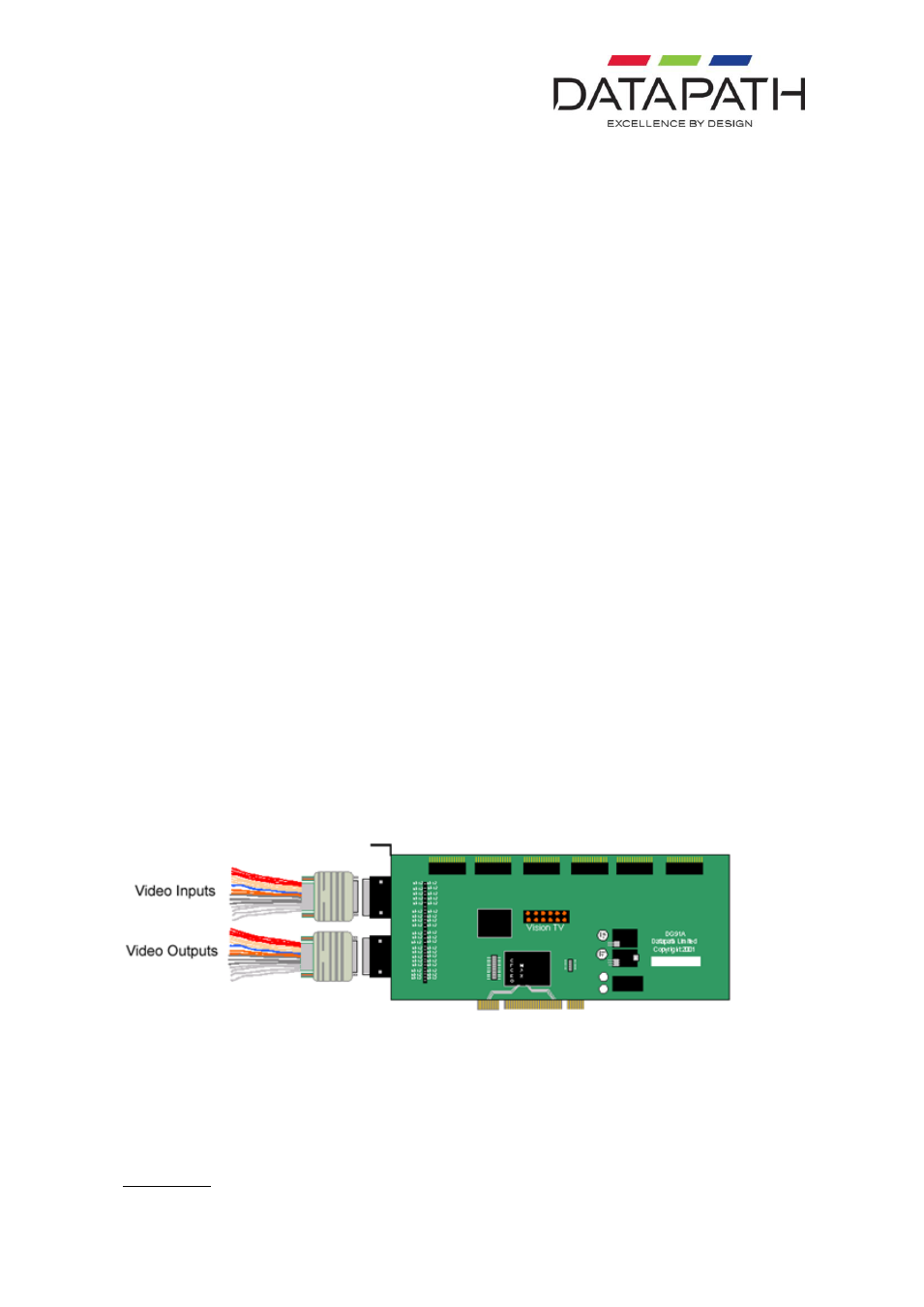
Video Inputs/ Outputs
The video signal is connected to the VisionSwitch using a 16-way splitter cable (provided). The
cable consists of 16 BNC sockets connected to a 26-way D plug.
The D plug should be connected to the Input socket on the back panel of the VisionSwitch. The
Input socket is the top socket. Each BNC socket is labelled to show the video input channel
number. i e. 1
– 16.
The Datapath VisionSwitch-SA is a stand alone, general purpose video switch. A second splitter
cable is provided to channel the video outputs from the card. The sockets on the back panel of the
card are identical; therefore the same type of splitter cable is used for both input and output.
The bottom D-connector located on the back panel is only used if outputs from the VisionSwitch-SA
are to be monitored. This would not be required if the VisionSwitch-H is used.
Jumper Links
There are a number of jumper links located on the face of the VisionSwitch card. Links 1 - 36 are
user selectable.
The user links provide the following functions:
Links 1 to 16