Connections, Operation with d6 or d12 – d&b T-SUB User Manual
Page 5
Connections
1
2
3
4
5
1
2
3
4
5
Sense Drive
n.c.
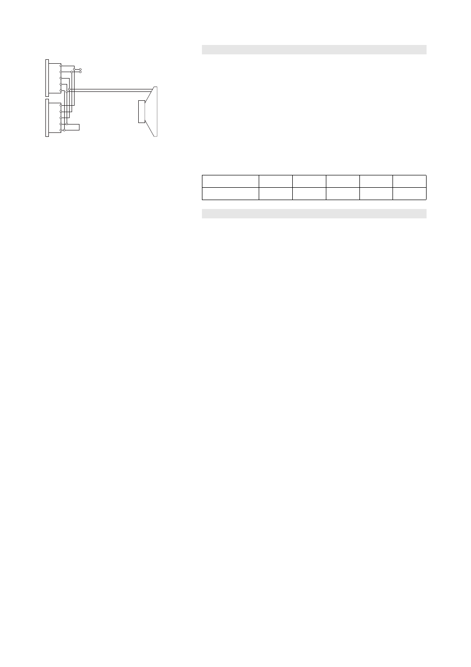
Fig. 2: Connector wiring
The T-SUB cabinet is fitted with a pair of EP5 connectors. All five pins of
both connectors are wired in parallel. The T-SUB uses the pin
assignments 3/4 and 5. Pin 5 is used for SenseDrive (only available
when using a D12 amplifier and 5-wire cabling). Pins 1/2 are
designated to d&b full range systems. Using the male connector as the
input, the female connector allows for direct connection to additional
loudspeakers.
The T-SUB can be supplied with NL4 output connectors as an option.
The D12 SenseDrive function is not available when using NL4
connectors.
Pin equivalents of EP5 and NL4 connectors are listed in the table below.
EP5
1
2
3
4
5
NL4
1+
1–
2+
2–
n.a.
Operation with D6 or D12
Select the controller setup T-SUB.
Within the D12 amplifier this is available in "Dual Channel" and "Mix
TOP/SUB" mode.
Up to a total of two T-SUB loudspeakers can be driven by each channel
of the D6 or D12 amplifiers.
Controller settings
100 Hz circuit
If the 100 Hz circuit is selected, the upper operating frequency of the
system is reduced from 140 Hz to 100 Hz.
T-SUB Manual
(1.0 EN)
Page 5 of 8