Casella CEL Software for the Tuff sampling pumps User Manual
Page 23
the message line at the bottom left of the display.
2.
Click the Pump button and select the Communications/option.
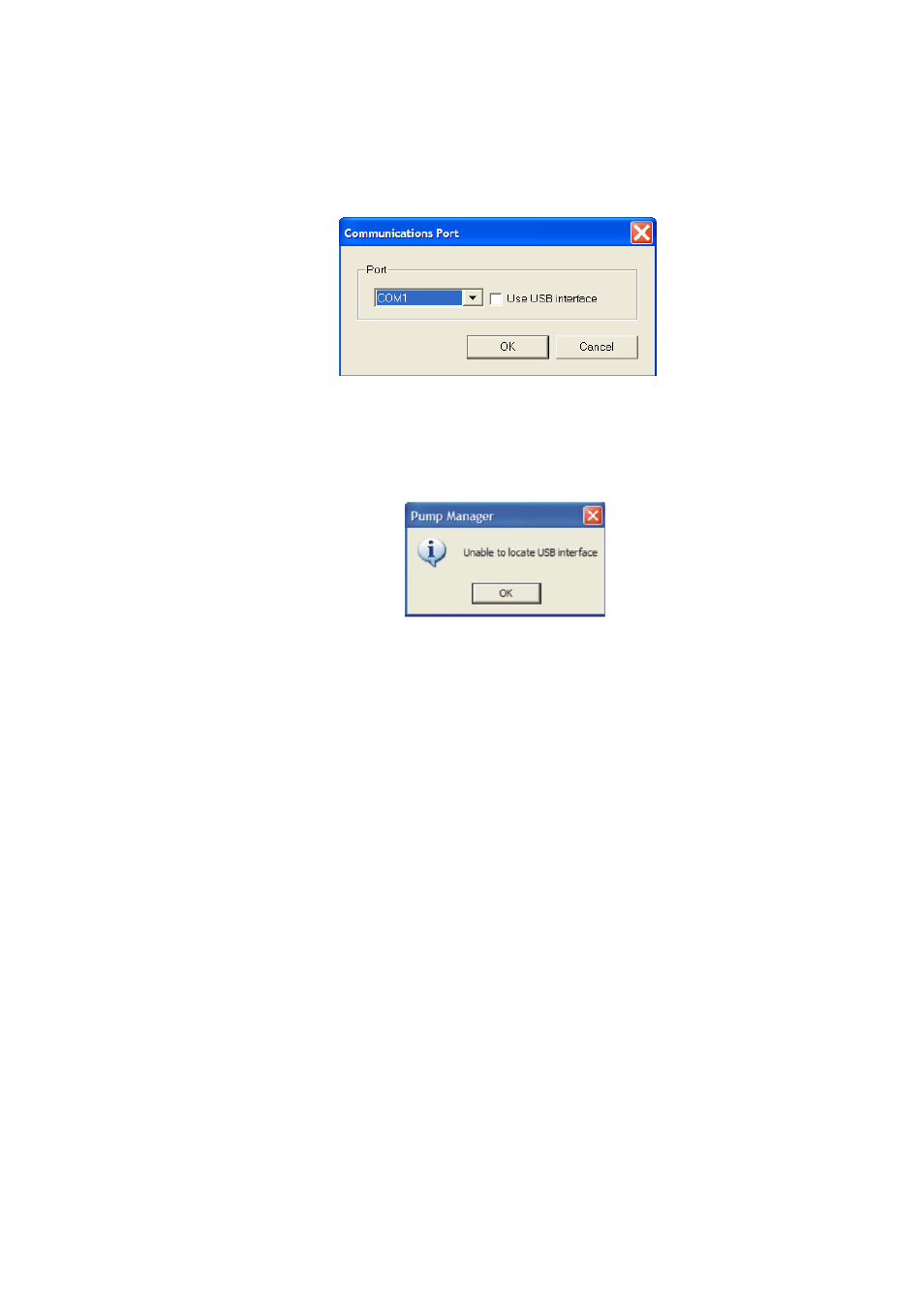
A Communication Port dialog is displayed (Fig. 33).
Figure 33 Communication Port Dialog
2. With the ‘Use USB interface’ option ticked, Pump Manager will automatically
detect the presence of a Casella IR Interface and use it to communicate with the
pump. If program is run without USB IR device fitted the following screen will be
seen (Fig. 32):
Figure 34 Program Run without USB IR Device Fitted
Leave this option un-ticked if you are using an earlier (RS-232 based) IR interface
(CMC39) and select the required COM port from the drop-down list.
Specify the port used by the IR link, then click OK to confirm the choice.
An active IR link icon should be shown in the System Tray to the right of the
Status Bar at the bottom of the PC display. This indicates that the device is
waiting to communicate with an TUFF Pump.
Best communication with the pump is achieved when the IR link is positioned in
line with the IR interface window of the pump, with the two devices no more than
60 cm (2 ft) apart.
The fold out sheet at the back of this book shows a diagram of the main menus
and options available from Pump Manager software.
D.
CONFIG. URING THE SOFTWARE AND ADDING A PUMP
Select a communication port then Add Pump (Fig. 34) and Add Person (Fig. 35)
identities to the software as follows.
1.
Select the Pump menu and see the following options.
Communications
Specifies the communication port to be used by the IR
Transducer
Program
Allows the TWA and the two user defined programs
available to the TUFF Pro to be edited and sent to the
pump as described in Section E
2. Select the Communications option and then choose the port to be used from
Casella CEL Limited
23