Installation – Desa RN30E-CAN User Manual
Page 6
6
105056
BLUE-FLAME VENT-FREE PROPANE/LP AND
NATURAL GAS GREENHOUSE CO2 GENERATOR
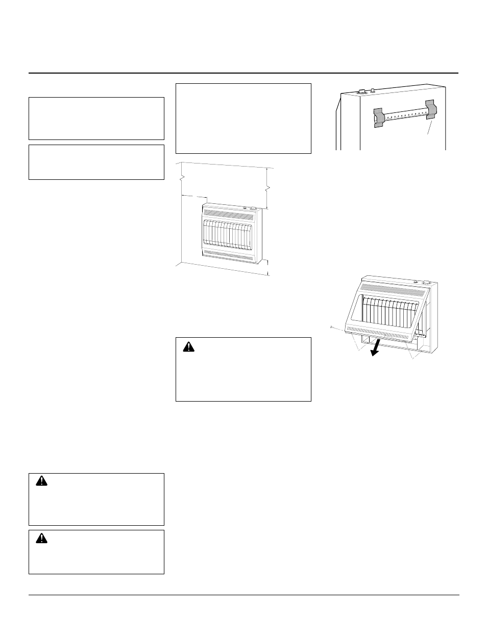
INSTALLING APPLIANCE TO
WALL
Mounting Bracket
The mounting bracket is located on back
panel of appliance. It has been taped there
for shipping. Remove mounting bracket from
back panel.
Figure 5 - Mounting Bracket Location
Removing Front Panel Of CO2
Generator
1.
Remove two screws near bottom cor-
ners of front panel.
2.
Lift straight up on grill guard until it stops.
Grill guard will slide up about 1/4".
3.
Pull bottom of front panel forward, then
down.
4.
Remove cardboard packing from grill
and heat shield.
Figure 6 - Removing Front Panel Of CO2
Generator
Methods For Attaching
Mounting Bracket To Wall
Only use last hole on each end of mounting
bracket to attach bracket to wall. These two
holes are 16 inches apart from their centers.
Attach mounting bracket to wall in one of
two ways.
1. Attaching to wall stud
2. Attaching to wall anchor
Attaching to Wall Stud:
This method
provides the strongest hold. Insert mounting
screws through mounting bracket and into
wall studs.
Attaching to Wall Anchor:
This method
allows you to attach mounting bracket to
hollow walls (wall areas between studs) or
to solid walls (concrete or masonry).
Decide which method better suits your needs.
Either method will provide a secure hold for
the mounting bracket.
Mounting
Bracket
CAUTION:
• appliance pilot and burner
must be at least 18 inches
above floor
• locate appliance where mov-
ing vehicle will not hit it
For convenience and efficiency, install CO2
generator
• where there is easy access for operation,
inspection, and service
• where strong wind gusts from an open
door or ventilator can not blow directly
into appliance.
*16
3
/
4
"
Figure 4 - Mounting Clearances As Viewed
From Front of Appliance
INSTALLATION
NOTICE: A qualified service per-
son must install appliance. Fol-
low all local codes.
CHECK GAS TYPE
Only use gas type specified on rating plate.
If your gas supply is different, do not install
appliance. Call dealer where you bought
appliance for proper type appliance.
INSTALLATION ITEMS
Before installing appliance, make sure you
have the items listed below.
• external regulator (Propane/LP Only,
supplied by installer)
• piping (check local codes)
• sealant (resistant to propane/LP gas)
• manual shutoff valve *
• ground joint union
• test gauge connection * (see Figure 13,
page 8)
• sediment trap
• tee joint
• pipe wrench
* An A.G.A. or C.G.A. design certified
manual shutoff valve with 1/8" NPT tap is
an acceptable alternative to test gauge con-
nection. Purchase the optional A.G.A. or
C.G.A. design certified manual shutoff valve
from your dealer. See Accessories, page 15.
LOCATING APPLIANCE
This appliance is designed to be mounted on
a wall.
Continued
WARNING: Maintain the mini-
mum clearances shown in Figure
4. If you can, provide greater clear-
ances from floor, ceiling, and join-
ing wall.
WARNING: Never install the
CO2 generator
• in a home
• in a recreational vehicle
IMPORTANT:
Vent-free CO2 generators add
carbon dioxide and moisture to the air.
36"
*
FLOOR
CEILING
Minimum
Minimum To Floor
6"
Minimum
From
Sides Of
Heater
Left
Side
Right
Side
NOTICE: The intended use of this
appliance is the generation of car-
bon dioxide inside greenhouses
for plant production.
• where flammable objects are
less than 36 inches from the
front, top, or sides of the appli-
ance
• in high traffic areas
• in windy or drafty areas