3 display elements and connections – AXING SKM 2-00 User Manual
Page 4
Common
SKM 2-00
© AXING AG – Stand: 10.11.08 – technische Änderungen und Irrtümer vorbehalten
Seite 4
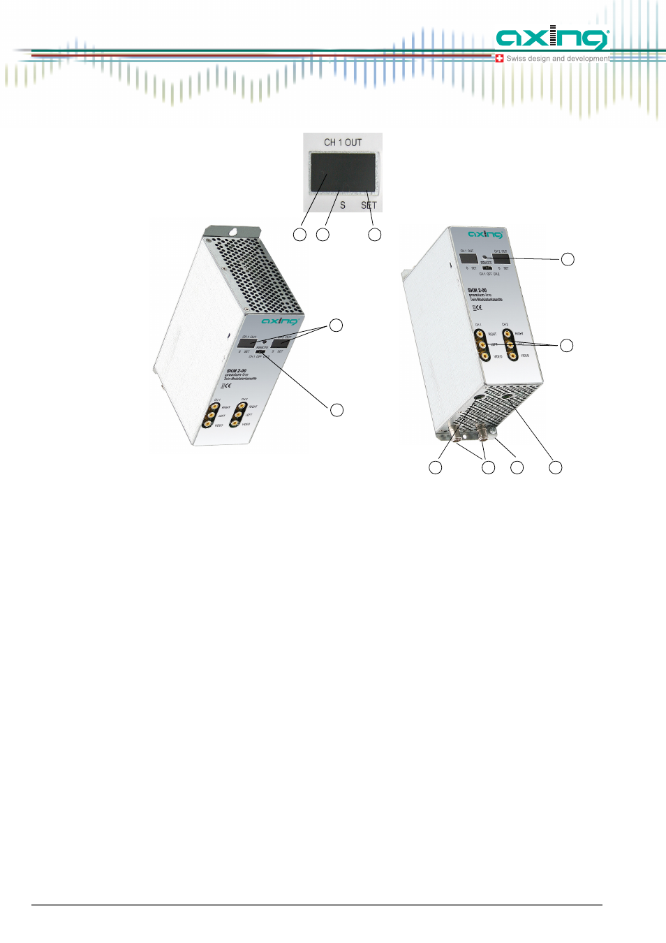
2.3 Display elements and connections
Fig. 2
Display elements and connections
1 Programming selection switch (duct 1 – position left, duct 2 – position right).
After completed programming, the switch must be in center position!
2 Display channel number
3 Display point special channels
4 Display point modulator programming
5 RF output and DC input (for installation in basic unit)
6 DC input/output (only for single operation)
7 DC input/output (power supply for three more twin modules in stand-alone operation (max. 4 twin
modules))
8 Audio/video outputs (Cinch)
9 Infrared receiver
10 Grounding screw
10
1
2
5
6
7
8
9
3
4
2
02