Start-up, 4start-up – AXING SKS 4-00 User Manual
Page 7
© AXING AG – state of the art: May 2012 – Reserving change in design and type
Page 7
Start-up
SKS 4-00/4-01/8-01
4
Start-up
Before inserting or changing a module, pull the mains plug of the headends basic unit from the socket!
Ground the base plate in order to avoid dangerous overvoltages according to EN 50083-1, EN 60728-
11:2010 (attention: risk of fire/death). Use the grounding screw 1 attached to the device.
To remove the casing cover, unscrew the two bottom screws 2. Now the casing cover can be folded
upwards and removed. The modules are inserted in the active output combiner 4 and fastened on the
top by means of a screw. Each free slot may be used. The power supply of the module is provided by the
active output combiner.
To remove the 19" mounting frame of the SKS 4-01, unscrew the four mounting screws from the rear side
3
.
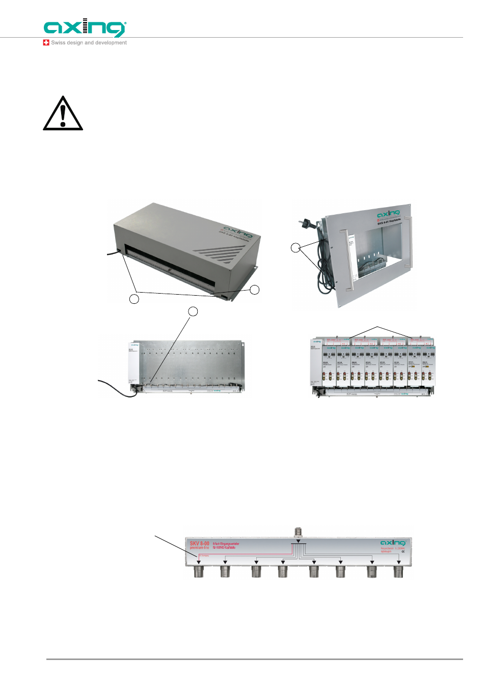
Fig. 4:
Installation of modules in SKS X-XX
It is possible to lead the receiving signals directly or via optionally available splitters (SKV 2-00/3-00/4-00/
8-00) to the inputs of the modules.
The required LNB control voltages and signals are provided by each channel of the modules for the
conversion of SAT signals. Therefore it is possible to use SAT multi switches for distributing the desired
SAT signals.
If using our input splitters (SKV 2-00/3-00/4-00/8-00), observe the DC power pass for the LNB supply
voltage and control.
Fig. 5:
DC power pass of the input splitters SKV 2-00/3-00/4-00/8-00
After module assembly and delivery of input signals, the cover or the 19" mounting frame can be mounted
again.
SKS 8-00 fully equipped
SKS 8-00 without modules
Input splitter SKV 2-00 to SKV 8-00
2
4
1
3
SKS 4-01 without
modules
Note
Output with DC
power pass (red)