Panel description, Front panel, Back panel – Atlona AT UHD M2C BAL User Manual
Page 4: Digital signal is identified 6. green led: dolby
DC 5V
ANALOG
DEFAULT
RS-232
LAN
ADJUST
HDMI OUT
R
+
+
-
-
L
FW
HDMI IN
DC 5V
ANALOG
DEFAULT
RS-232
LAN
ADJUST
HDMI OUT
R
+
+
-
-
L
FW
HDMI IN
4
atlona.com
Toll free: 1-877-536-3976
Local: 1-408-962-0515
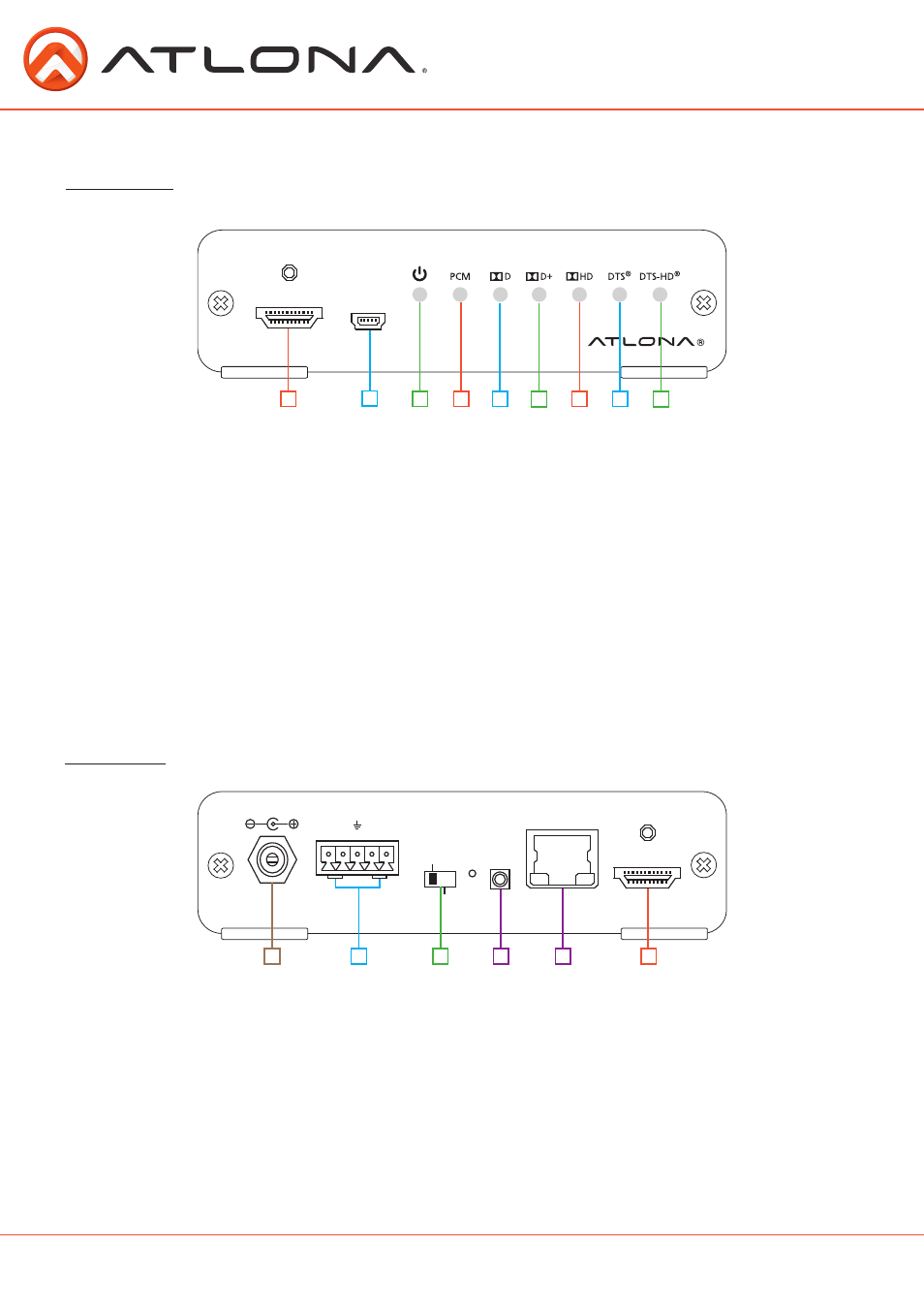
Panel Description
Front Panel
1. HDMI Input port: Connect HDMI source here
2. Mini USB port: Firmware update port, connect a Mini USB to USB A cable to a computer
3.
Red LED:
Illuminates when receiving power
4.
Green LED:
will illuminate when a PCM audio signal is detected
5.
Green LED:
illuminates when a Dolby
®
Digital signal is identified
6.
Green LED:
Dolby
®
Digital Plus signal indicator
7.
Green LED:
illuminates when receiving a Dolby
®
TrueHD signal
8.
Green LED:
light will illuminate when a DTS Digital Surround™ is present
9.
Green LED:
signal light will turn on when DTS-HD Master Audio™ signal is received
NOTE: LED signifies incoming digital audio signal type only. The M2C-BAL does not decode
Dolby or DTS signals on pass through. The M2C-BAL will decode Dolby and DTS, down
mix it to one/two channel, and send that signal to either the HDMI output or the analog
output.
1
2
3
4
5
6
7
8
9
Back Panel
1. DC 5V: Connect included locking 5V DC power supply here.
2. L/R audio port: Connect to an amplifier, mixer, DSP, or other audio input
3. Control Switch: Switch between adjust and default modes
Adjust - Allows the M2C-BAL volume to be controlled through RS-232 or TCP/IP
Default - Factory neutral settings, volume cannot be controlled by RS-232 or TCP/IP
*Gain will be set to 0 and EQ will be flat
4. RS-232 port: Connect control system to RS-232 port
3.5mm pin out - Tip: 2 (TX), Ring: 3(RX), Sleeve: 5 (Ground)
5. LAN port: Connect network switch or router to this port for TCP/IP or WebGUI control
6. HDMI out port: Connect to an HDMI display, extender, or switcher
1
2
3
4
5
6